Hulp of advies nodig?![]() +44 (0)1782 454499
+44 (0)1782 454499
PRODUCTEN DIE IN DIT PROJECT ZIJN GEBRUIKT
Hoewel het niet per se een uitputtende lijst is, werden de volgende gereedschappen en materialen, geleverd door Easy Composites, in dit project gebruikt.
De hieronder getoonde hoeveelheid is de geschatte hoeveelheid die in het project is gebruikt, afgerond naar de dichtstbijzijnde beschikbare kitgrootte of hoeveelheid.
MATERIALEN & VERBRUIKSARTIKELEN
GEREEDSCHAP & APPARATUUR
VERSTERKINGEN
MATERIALEN VOOR HET MAKEN VAN MALLEN
VIDEO-HANDLEIDING
Een Fietsframe van Koolstofvezel Maken van Begin tot Eind
Diepgaand technisch interview met fietsontwerper en composietenliefhebber Vlad Yordinov, waarin het proces wordt besproken en uitgelegd van het maken van een productieklaar, raceklaar koolstofvezelframe voor een downhill mountainbike, van het oorspronkelijke CAD-ontwerp tot de uiteindelijke afwerking.
In deze video van 40 minuten laat Vlad ons zien hoe hij zijn originele ontwerp omzette in een afgewerkte fiets zonder de noodzaak van investeringen in enorm dure massieve aluminium gereedschappen die over het algemeen door grote fabrikanten worden gebruikt om koolstofvezel fietsframes te maken. Door veel minder dure composietgereedschappen te gebruiken en het laminaat uit te harden onder vacuümdruk in plaats van positieve druk van een opblaasbare blaas, is Vlad in staat om een hoogwaardig fietsframe te produceren voor minder dan 1/10 van de typische kosten om zelfs een prototype koolstof fietsframe te produceren.
OVERZICHT TUTORIAL
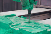
1. Patronen bewerkt uit tooling board
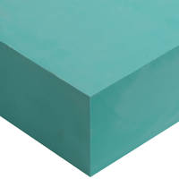
Zodra het ontwerp van het frame en het patroon is bepaald, kan het worden bewerkt uit tooling board. Voor dit proces wordt epoxy tooling board gebruikt, omdat het de eigenschappen heeft die nodig zijn om het te kunnen gebruiken bij de productie van koolstofvezel tooling met behulp van een speciale tooling pre-preg.
De plaat zelf wordt bewerkt met een 3-assige machine. In dit geval is het ontwerp zodanig dat alleen een 3-assige machine nodig is voor de vorm en details. Voor complexere projecten kan een 5-assige machine nodig zijn.
De machine snijdt de plaat in verschillende fasen, beginnend met een zeer grove snede voordat de bewerkingen worden herhaald met steeds fijnere sneden totdat het model volledig uit het blok is bewerkt. De afwerking van het bewerkingsproces zal echter verdere handmatige nabewerking en afdichting vereisen om een voldoende hoge kwaliteit te verkrijgen voor het vormproces.
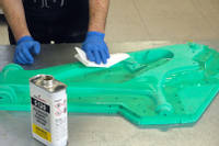
2. Afwerken en afdichten van de modellen
Na de bewerking moet het patroon gladgemaakt worden door het oppervlak te schuren totdat de gewenste afwerking is bereikt. Het patroon moet vervolgens worden verzegeld om een glanzend, afgedicht oppervlak te verkrijgen dat klaar is om van te mallen.
Meerdere lagen afdichtmiddel worden gebruikt op het hoofddeel van het model om de hoogwaardige, hoogglans afwerking te verkrijgen. Typisch worden slechts 2 lagen afdichtmiddel gebruikt op de flenzen; dit om te garanderen dat bij het samenvoegen van de mal een zeer hoge mate van nauwkeurigheid en precisie op de contactoppervlakken aanwezig is.
Vanwege de complexiteit van het frame is het noodzakelijk om inzetstukken in de mal te gebruiken om ervoor te zorgen dat ondersnijdingen en bepaalde complexe details correct worden gevormd. Deze gebieden vereisen ook een hoge precisie en mogen daarom slechts enkele lagen bevatten.
Er zijn gaten in de mal geboord om metalen uitlijningsinzetstukken te kunnen plaatsen. Dit is om ervoor te zorgen dat, zodra de mallen zijn gemaakt, ze perfect zijn uitgelijnd, zodat de gaten kunnen worden gebruikt om de malhelften precies in de juiste positie aan elkaar te bouten. De gaten zijn zo dicht mogelijk bij de rand van het gereedschapsonderdeel geplaatst, zodat de klemkracht rond de kritieke verbindingsgebieden consistent is.
3. De negatieve mallen maken
De mal wordt gemaakt van het XPREG XT135 Tooling pre-preg systeem. Dit bestaat uit een oppervlaktelaag en een ruglaag. In dit geval wordt één laag oppervlakteply gebruikt en vervolgens werd de oppervlakteply ondersteund met 5 lagen rugply om een goede sterke en stijve mal te verkrijgen.
Om de oppervlaktelaag in de moeilijke hoeken en strak rond de pinnen te krijgen, worden stroken oppervlaktelaag met de vezels georiënteerd onder een hoek van 45 graden in die moeilijke gebieden gebruikt. De rest van de oppervlaktelaag wordt vervolgens opgebouwd. In dit geval, vanwege de complexe vorm en de kritische nauwkeurigheid van het matrijs-proces, werd de matrijs ontlucht door deze in een vacuümzak met een geperforeerde lossingsfolie te plaatsen en er vacuüm op te trekken. Dit helpt om al het pre-preg materiaal in de krappe hoeken te krijgen.
De ruglagen worden vervolgens opgebouwd totdat alle 5 lagen zijn voltooid. Regelmatig ontluchten helpt bij de vezelconsolidatie en zorgt ervoor dat er geen holtes in de lay-up ontstaan.
De mal is nu klaar om uitgehard te worden en wordt vacuüm verpakt en uitgehard bij 60°C voor de initiële uithardingscyclus bij lage temperatuur. De reden dat deze niet op het model bij een hogere temperatuur wordt uitgehard, is dat epoxy tooling block bij hogere temperaturen licht zal uitzetten, wat zal leiden tot meer dimensionale onnauwkeurigheid.
In dit stadium wordt de mal uit het patroon ontvormd. Het toolingblok komt er over het algemeen vrij gemakkelijk uit. De pennen zitten echter stevig vast en vereisen zorg en tijd om te verwijderen. Grijpers kunnen worden gebruikt om ze eruit te trekken, maar een goede techniek in dit geval was het ronddraaien en eruit draaien met behulp van een boormachine.
Hetzelfde proces wordt herhaald voor de tweede helft van de mal. Zodra beide helften zijn ontkist en bijgesneden, zijn ze klaar voor de post-uitharding. De post-uitharding voltooit de uitharding van de mal zelf en zorgt ervoor dat deze kan worden gebruikt bij de hoge uithardingstemperatuur van de pre-preg voor het uiteindelijke onderdeel. In dit geval, aangezien het een gespleten mal betreft, worden beide helften aan elkaar geschroefd voor de post-uitharding. Dit is om ervoor te zorgen dat de montagevlakken perfect uitgelijnd zijn en niet onder onnodige spanning komen te staan wanneer ze in gebruik aan elkaar worden geschroefd.
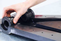
4. Malinzetstukken
Malinzetstukken zijn noodzakelijk in bepaalde gebieden, zoals waar het frame splijt. Het inzetstuk zorgt ervoor dat het gebied rond de splitsing correct als één geheel kan worden gevormd. De inzetstukken vergemakkelijken ook het algehele ontmallen in dergelijke complexe delen van het frame.
Vergelijkbaar met de hoofdvorm wordt een patroon voor het inzetstuk gefreesd uit een toolingblok. Vervolgens wordt een additie-uithardende siliconen gebruikt om een mal van het patroon te maken. Eenmaal uitgehard, kan de mal gemakkelijk van het patroon worden losgemaakt en is nu klaar om het inzetstuk te maken.
Het inzetstuk is gegoten uit hoge-temperatuur epoxy en gefreesd koolstof/grafietpoeder. Dit voegt sterkte toe aan het inzetstuk en, door een grote hoeveelheid koolstof in het inzetstuk te hebben, betekent dit dat het inzetstuk een vergelijkbare CTE zal hebben als de koolstofmal, wat betekent dat ze tijdens het uithardingsproces op vergelijkbare wijze zullen uitzetten en krimpen.
Het gegoten inzetstuk moet worden gladgemaakt en oppervlakteverzegeld met de S120 om een gepolijste hoogglansafwerking te verkrijgen. Daarna wordt het voorzien van een lossingslaag en is het klaar voor gebruik. Een voordeel van het gebruik van inzetstukken die uit een siliconenmal zijn gegoten, is dat, indien nodig, het inzetstuk tijdens het ontmallen kan worden gebroken of vernietigd om het frame te redden, maar toch snel opnieuw kan worden gegoten met behulp van de siliconenmal.
5. Het lamineren van het frame
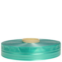
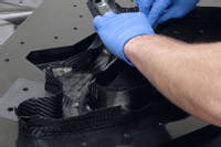
De frame-lay-up voor dit ontwerp maakt gebruik van een mix van geweven twill pre-preg stoffen en unidirectionele pre-preg stoffen. De eerste stap is het voorbereiden van sjablonen voor de oppervlaktelaag van geweven pre-preg. Dit wordt handmatig gesjabloneerd en is cruciaal om de vezeloriëntatie te laten overeenkomen tussen mallen en secties binnen elke mal, aangezien het een zichtbare cosmetische laag is.
Twee geweven lagen worden in de mallen gelegd, waarbij de eerste laag volgens de sjablonen wordt georiënteerd. De mallen worden vervolgens ontlucht voordat de tweede laag wordt aangebracht. De tweede laag wordt onder een hoek van 45° georiënteerd om torsie- en wringsterkte toe te voegen.
Sjablonen voor de UD pre-preg worden gemaakt en de pre-preg wordt in één keer uitgesneden. In een frame van deze grootte zitten meer dan 200 stukken pre-preg weefsel. Het UD-doek voegt veel sterkte toe in de richting waarin de vezels zijn georiënteerd. Aangezien dit frame ring- en torsiesterkte heeft van de geweven lagen, is het grootste deel van het UD-weefsel in de hoofdbuizen uitgelijnd langs de lengte van de buizen om stijfheid te bieden. De UD-oriëntatie wordt rond bevestigingen en beugels gedraaid in de specifieke richtingen waarin de krachten in die gebieden zullen uitkomen. Over het algemeen zullen de hoofdbuizen van een dergelijk frame 2 geweven oppervlaktelagen, 4 UD-lagen en een laatste binnenste geweven laag hebben. Aangezien het een prototypeframe betreft, is het waarschijnlijk dat na testen het aantal lagen in veel gebieden zal worden verminderd voor later geproduceerde frames.
In structureel kritieke gebieden worden extra lagen materiaal gebruikt voor extra sterkte, en de oriëntatie wordt gevarieerd om aan de belastingstrajecten te voldoen. Bijvoorbeeld rond veel van de pennen wordt het UD-weefsel geroteerd, zodat bij ontvorming en gebruik het gatgebied zeer sterk is, aangezien er geen doorgesneden vezels rond het gat zelf zijn. Specifieke lay-up overweging is nodig rond de vele inserts, zowel voor de sterkte en belastingen die die gebieden zullen opnemen als voor de verwerking van het onderdeel. Sommige gebieden zijn ontoegankelijk voor vacuümzakken en zijn daarom afhankelijk van de compressie van de insert en de mal om de vezels correct te consolideren.
Overlappende verbindingen worden op de mallen gecreëerd. Dit wordt gedaan zodat, wanneer de mallen worden samengevoegd, er voldoende sterkte is in de gebieden waar het frame wordt samengevoegd. De overlapping is taps toelopend over de breedte en meerdere lagen om ervoor te zorgen dat de overlappende verbinding zijn sterkte behoudt. Tot slot worden in dit stadium enkele van de uiteindelijke inzetstukken gelamineerd en op hun plaats gemonteerd.

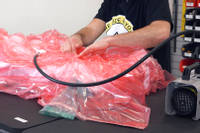
6. Interne vacuümzakken
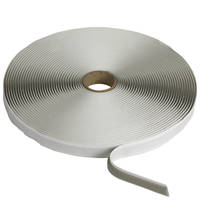
Bij grootschalige productie zou voor deze fase doorgaans een blaas worden gebruikt; de blazen worden echter speciaal geproduceerd en vereisen het gebruik van dure billet-gereedschappen. Voor kleine serieproductie is het gebruik van vacuümzakken beter haalbaar.
Buisvormige vacuümzakfolie wordt opgemeten en op maat gesneden. Eén uiteinde van elke buis wordt vervolgens hitteverzegeld om het aan die kant luchtdicht te maken. Bij gebruik van deze zakfolie is het noodzakelijk om lossingsfolie aan te brengen op een deel van de mal. Dit is zodat, wanneer het vacuüm wordt getrokken, de zakfolie vrij kan glijden en schuiven over het oppervlak terwijl het uitzet en over het maloppervlak drukt. Er moet zorgvuldig worden getrimd om te voorkomen dat de lossingsfolie per ongeluk over de overlappende verbindingsoppervlakken terechtkomt, wat hechtingsproblemen en een zwak punt in het frame zou kunnen veroorzaken. Om deze reden wordt de folie alleen aangebracht op de zijde met overlappen.
De zak wordt voorzichtig in elke buis gelegd, waarbij ervoor wordt gezorgd dat er voldoende overschot is om deze goed te laten uitzetten. Op plaatsen waar de uiteinden van de zak samenkomen, is er een kleine overlap, zodat wanneer het vacuüm wordt getrokken, elk deel van de mal bedekt is met de zak.
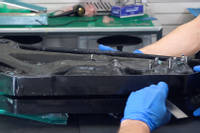
7. Sluiten van de mallen
Deze fase is cruciaal, aangezien verkeerd uitgelijnde overlappen of een vastzittende vacuümzakbuis het hele project kunnen ruïneren. De overlappen en de zak moeten zo goed mogelijk worden ingevouwen om ervoor te zorgen dat er geen materiaal op de flens ligt.
De mal wordt met een kleine opening vastgehouden, zodat u door de opening kunt kijken om er zeker van te zijn dat er geen materiaal vastzit. Met een plat gereedschap is het mogelijk om materiaal dat iets verplaatst moet worden te manipuleren. De mal wordt vervolgens volledig gesloten.
De twee malhelften worden uitgelijnd door middel van pennen die rond de mal zijn geplaatst. De twee helften worden vervolgens aan elkaar geschroefd.
8. Externe vacuümzak
In dit stadium moet de gehele mal in een vacuümzak worden geplaatst. De 4 stukken buisvormige zak moeten door de afdichting van de hoofdvacuümzak gaan. Dit is zodat de binnenkant van de buisvormige zakken open is naar de atmosfeer, zodat, wanneer er een vacuüm op de hoofdzak wordt getrokken, de buisvormige folie door atmosferische druk tegen de binnenkant van de buizen in de mal wordt gedrukt.
Zodra de zak is afgesloten, kan er vacuüm op de zak worden getrokken. Er moet zorgvuldig worden gecontroleerd of de vacuümfolie in alle juiste hoeken aan de buitenkant van de mal komt en dat er geen bruggen in de folie zijn. Daarna moet een lektest worden uitgevoerd om ervoor te zorgen dat de zak goed is afgesloten. De zak wordt vervolgens een nacht gelaten om te ontluchten (debulk). Zodra het ontluchten succesvol is uitgevoerd, is de mal klaar om in de oven te worden uitgehard.
9. In de oven uitharden en ontmallen
Aangezien het gemaakt is met XPREG XC110, wordt de standaard verlengde uithardingscyclus gebruikt voor de ovenuitharding. De zak blijft tijdens de gehele uitharding vacuüm verbonden en vervolgens wordt de cyclus op het onderdeel uitgevoerd. Eenmaal volledig uitgehard en afgekoeld, is het klaar om ontkist te worden.
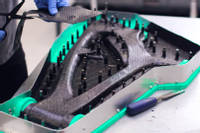
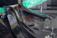
Om te ontmallen, wordt de zak van de mal verwijderd en worden de bouten die elke helft bij elkaar houden, losgemaakt. De borgpennen worden eruit getikt en vervolgens worden, met behulp van ontmalwiggen, de twee helften langzaam gescheiden. Op dit punt kan het fietsframe voorzichtig uit de mal worden verwijderd.
Op dit punt worden de inzetstukken verwijderd. Ze tikken er relatief gemakkelijk uit, gebruikmakend van de loshoeken in het frameontwerp voor een eenvoudige lossing. Het frame is dan klaar voor inspectie en voor het bijsnijden van de gietnaden en randen, voorafgaand aan het schilderen en de uiteindelijke montage.
10. De achterdriehoek
De basismethode en technieken die worden gebruikt voor de achterdriehoek zijn in principe identiek aan die van het hoofddeel van het frame. Het belangrijkste verschil is de opbouw van de pre-preg, die afwijkt van het frame met meer UD naar de buitenkant van de buis. De kleinere afmeting betekent dat de overlappende verbindingen zo zijn ontworpen dat de opbouw, eenmaal uitgehard, gelijkmatig zal zijn.
Hetzelfde vacuümzakproces, waarbij de hoofdvacuümzak en de buisvormige vacuümzakfolie worden gebruikt, wordt uitgevoerd met dezelfde uithardingscyclus. In dit geval is de achterdriehoek gemaakt van 2 delen.
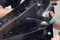
Eenmaal uitgehard worden de achterdriehoeken ontbraamd en bijgesneden, klaar om aan elkaar te worden gehecht. Voor een toepassing als deze is de VM100 Zwarte methacrylaatlijm perfect als constructielijm. Aangezien dit een prototype frame is, is er nog geen mal, dus wordt het frame geassembleerd zodat de achterdriehoeken aan elkaar kunnen worden geschroefd om een juiste uitlijning te garanderen terwijl de lijmverbinding uithardt.
11. Afwerking en lak
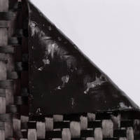
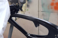
In dit stadium is het belangrijkste composietwerk gedaan. Het frame wordt nu afgewerkt met een lichte schuur- en polijstbeurt voordat het wordt gespoten met een satijnen lak. In dit geval wordt geen andere verf gebruikt, aangezien we de ruwe koolstofafwerking onder de blanke lak wilden laten zien.
Het frame kan vervolgens worden geassembleerd met alle lagers, koppelingen, beugels en onderdelen om een complete fiets te maken. Het werd vervolgens getest en gebruikt in races, waarbij de feedback werd gebruikt om het ontwerp en de lay-up aan te passen voor het productiemodel.
DISCUSSIE (24)
Deel al uw vragen of opmerkingen over deze videohandleiding.
Koolstofvezel fietsframes zijn extreem complexe componenten om te maken, met veel smalle buissecties, nauwkeurige details en precies geplaatste inzetstukken. De complexiteit van de layup betekent dat lamineren in een mal, op de manier zoals getoond in deze video, alleen echt kan worden gedaan met behulp van prepreg, dat nauwkeurig kan worden gesneden en geplaatst zonder tijdsdruk. Het zou vrijwel onmogelijk zijn om hetzelfde te doen door droge vezels en natte epoxyhars (in meerdere lagen) met de hand te lamineren in de twee malhelften – met overlappingen – rond voorgemaakte vacuümzakbuizen en vervolgens de twee mallen samen te sluiten voordat het vacuüm wordt getrokken en uitgehard.
Als u op zoek bent naar een handlaminatiemethode voor het maken van een fietsframe, zou een realistischere optie zijn om een nauwkeurig gevormde schuimkern te produceren en vervolgens koolstofvezel en hars op de buitenkant van de schuimkern te lamineren. Dit zou vervolgens kunnen worden omwikkeld met een krimptape om de vezel te consolideren of eventueel vacuüm verpakt kunnen worden. Een dergelijk proces is uiteraard niet zonder compromissen (de kern zou in het frame blijven, de nauwkeurigheid van het frame en de afwerking zouden afhangen van veel handwerk aan de buitenkant van het laminaat, enz.), maar het zou realistischer zijn dan proberen een dergelijk complex en ontoegankelijk onderdeel nat te lamineren en vervolgens vacuüm te verpakken.
Over het algemeen is ongeveer 20 gew.% grafiet en 20 gew.% gemalen koolstof ongeveer het maximale dat u aan het mengsel kunt toevoegen voordat het te dik wordt om goed te kunnen gieten.
EEN OPMERKING OF VRAAG ACHTERLATEN
PRODUCTEN DIE IN DIT PROJECT ZIJN GEBRUIKT
Hoewel het niet per se een uitputtende lijst is, werden de volgende gereedschappen en materialen, geleverd door Easy Composites, in dit project gebruikt.
De hieronder getoonde hoeveelheid is de geschatte hoeveelheid die in het project is gebruikt, afgerond naar de dichtstbijzijnde beschikbare kitgrootte of hoeveelheid.
MATERIALEN & VERBRUIKSARTIKELEN
GEREEDSCHAP & APPARATUUR
VERSTERKINGEN
MATERIALEN VOOR HET MAKEN VAN MALLEN
DISCUSSIE (24)
Deel al uw vragen of opmerkingen over deze videohandleiding.
Koolstofvezel fietsframes zijn extreem complexe componenten om te maken, met veel smalle buissecties, nauwkeurige details en precies geplaatste inzetstukken. De complexiteit van de layup betekent dat lamineren in een mal, op de manier zoals getoond in deze video, alleen echt kan worden gedaan met behulp van prepreg, dat nauwkeurig kan worden gesneden en geplaatst zonder tijdsdruk. Het zou vrijwel onmogelijk zijn om hetzelfde te doen door droge vezels en natte epoxyhars (in meerdere lagen) met de hand te lamineren in de twee malhelften – met overlappingen – rond voorgemaakte vacuümzakbuizen en vervolgens de twee mallen samen te sluiten voordat het vacuüm wordt getrokken en uitgehard.
Als u op zoek bent naar een handlaminatiemethode voor het maken van een fietsframe, zou een realistischere optie zijn om een nauwkeurig gevormde schuimkern te produceren en vervolgens koolstofvezel en hars op de buitenkant van de schuimkern te lamineren. Dit zou vervolgens kunnen worden omwikkeld met een krimptape om de vezel te consolideren of eventueel vacuüm verpakt kunnen worden. Een dergelijk proces is uiteraard niet zonder compromissen (de kern zou in het frame blijven, de nauwkeurigheid van het frame en de afwerking zouden afhangen van veel handwerk aan de buitenkant van het laminaat, enz.), maar het zou realistischer zijn dan proberen een dergelijk complex en ontoegankelijk onderdeel nat te lamineren en vervolgens vacuüm te verpakken.
Over het algemeen is ongeveer 20 gew.% grafiet en 20 gew.% gemalen koolstof ongeveer het maximale dat u aan het mengsel kunt toevoegen voordat het te dik wordt om goed te kunnen gieten.
EEN OPMERKING OF VRAAG ACHTERLATEN
100% VEILIG
BETAALMETHODEN
Easy Composites EU B.V., geregistreerd in Nederland 73601195. Alle inhoud auteursrecht (C) Easy Composites Ltd, 2025. Alle rechten voorbehouden.