Hulp of advies nodig?![]() +44 (0)1782 454499
+44 (0)1782 454499
PRODUCTEN DIE IN DIT PROJECT ZIJN GEBRUIKT
Hoewel het niet per se een uitputtende lijst is, werden de volgende gereedschappen en materialen, geleverd door Easy Composites, in dit project gebruikt.
De hieronder getoonde hoeveelheid is de geschatte hoeveelheid die in het project is gebruikt, afgerond naar de dichtstbijzijnde beschikbare kitgrootte of hoeveelheid.
VERSTERKINGEN
GEREEDSCHAP & APPARATUUR
VACUÜMZAKBENODIGDHEDEN
VIDEO-HANDLEIDING
Lamineren en Verpakken van een Koolstofvezelbuis met een Gedeelde Mal
In deze video-tutorial bekijken we gedetailleerd hoe je buisvormige composietcomponenten lamineert en vervolgens vacuümzakken gebruikt met behulp van een split-malproces met een interne vacuümzak.
Dit proces kan worden gebruikt om niet-rechte buisvormen te produceren, zoals koolstofvezel sturen, kajakpeddels en inductiebuizen. Het kan ook worden gebruikt voor zeer complexe buisvormige structuren, zoals koolstofvezel fietsframes en draagarmen. Deze video is bedoeld om een meer gedetailleerde kijk te geven op de lamineringsmethodologie en de principes van vacuümzakken die worden gebruikt in onze video-tutorial over het maken van een koolstofvezel fietsframe.
In situaties waar alleen een rechte buisvorm vereist is, zou de roll-wrapped buisproductiemethode vaak geschikter zijn, of in commerciële productieprocessen zoals pultrusie of pulwinding, kan ook worden gebruikt. Geen van deze processen kan echter worden gebruikt voor gebogen/gebogen buizen of complexe buisvormige structuren.
ACHTERGROND
Hoe zit het met interne bladders?
Deze methode is een alternatief voor de interne methode met drukblazen die vaak wordt gebruikt bij de productie van fietsframes. Deze methode vereist veel grotere mallen, meestal machinaal bewerkt uit massieve blokken aluminium, die bestand moeten zijn tegen de vervorming die wordt veroorzaakt door de onevenwichtige druk van de interne bladder.
Door de druk gelijkmatig aan de binnen- en buitenkant van de mal uit te oefenen, veroorzaakt deze interne vacuümzakmethode weinig tot geen vervorming van de mal, waardoor veel lichtere – en goedkopere – mallen kunnen worden gebruikt.
Hoe zit het met uitharding in een autoclaaf?
Hoewel we in deze handleiding het proces demonstreren met alleen vacuümdruk waarbij het onderdeel vervolgens wordt uitgehard in een conventionele oven (bekend als out-of-autoclave prepreg), kan exact hetzelfde proces worden gebruikt - en wordt het gebruikt - voor het onder hoge druk uitharden van buis- en framestructuren in een autoclaaf. Voor autoclaaf uitharding is het niet nodig om de materialen, de lay-up of het vacuümzakproces dat in deze handleiding wordt getoond, te wijzigen.
Net als bij de uitharding buiten de autoclaaf met alleen vacuüm, creëert uitharding in de autoclaaf met dezelfde interne vacuümzakconfiguratie ook gelijke druk aan beide zijden van de mal, waardoor deze lichtere composietmallen kunnen worden gebruikt.
Moet het prepreg zijn?
Het maken van complexe koolstofvezel buis- of framevormen gebeurt bijna uitsluitend met behulp van het prepreg vormproces. De reden hiervoor is vooral te wijten aan de praktische aspecten van het nauwkeurig snijden, hanteren en positioneren van de versteviging in de split-mal, het manipuleren van deze versteviging wanneer de mal is gesloten en vervolgens het werken rond de versteviging om de vacuümzak benodigdheden te positioneren. Al deze processen zouden moeilijk of bijna onmogelijk zijn als ze zouden worden uitgevoerd met behulp van een traditionele natte-layup methode of alternatieve vacuümvormprocessen zoals harsinfusie van droge stof.
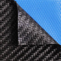
In deze video gebruiken we de XPREG XC110 out-of-autoclave koolstofvezel prepreg, die in de oven wordt uitgehard met behulp van een oplopend temperatuurprofiel tot 120°C; video-tutorial over het maken van prepreg koolstofvezel onderdelen out-of-autoclave hier.
Geschikte gereedschap/mal materialen
Omdat deze handleiding koolstof weefsel prepreg gebruikt, moet het onderdeel in een oven bij verhoogde temperatuur worden uitgehard. Het is daarom essentieel dat het materiaal waarvan de mal is gemaakt een voldoende hoge gebruikstemperatuur heeft. De mal die in deze handleiding wordt gebruikt, is gemaakt met behulp van ons XT135 out-of-autoclave koolstof weefsel tooling prepreg systeem; video tutorial over het maken van prepreg koolstof weefsel tools out-of-autoclave hier.
Als alternatief kan de mal met de hand worden gelamineerd met behulp van een hoogtemperatuur epoxy tooling systeem, zoals onze EG160/EL160/EMP160 producten; video-tutorial over het met de hand lamineren van een hoogtemperatuur epoxy mal hier.
OVERZICHT TUTORIAL
1. Sjablonen maken en de eerste laag prepreg snijden
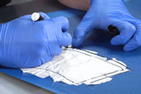
Om een benaderende vorm te krijgen om de prepreg versteviging op maat te snijden, wordt maskeertape aangebracht op het oppervlak van één helft van de split-mal. De maskeertape wordt vervolgens verwijderd en op de prepreg versteviging geplaatst. Omdat het sjabloon nog niet nauwkeurig is, wordt het in alle richtingen met ongeveer 1 cm verlengd.
De prepreg met ruwe vorm wordt vervolgens in de mal gelamineerd. Zodra deze volledig op zijn plaats zit, wordt alle overhangende versteviging zorgvuldig afgesneden, zodat de versteviging precies op maat is gesneden, gelijk met de rand van de spleet.
De reststukken koolstofvezel worden vervolgens terug op het backingpapier geplaatst, zodat het papier kan worden gesneden om een nauwkeurig sjabloon te maken dat precies aangeeft hoe de versteviging in de mal valt. Dit sjabloon kan worden bewaard voor toekomstig gebruik.
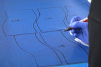
2. Sjablonen maken voor de verspringende overlappingen
Bij het lamineren van versteviging in een splitmal is het essentieel dat het grootste deel van de versteviging over de splitlijn doorloopt, om een zwak punt bij deze verbinding te vermijden. Zonder enige overlapping van de versteviging zouden de twee helften van het onderdeel simpelweg uit elkaar vallen!
Lagen versteviging die over de splitlijn doorlopen, worden de overlappingen of 'laps' genoemd. Om te voorkomen dat er andere zwakke punten in het laminaat ontstaan, worden deze overlappingen zelf versprongen door ze verschillende afmetingen te geven. In de tutorial worden de overlappende stukken versteviging 5mm, 10mm en 15mm breder gesneden dan de splitlijn.
Om te proberen een consistente wanddikte rond de buis te behouden, worden de overeenkomstige stukken versteviging voor de andere helft van de buis smaller gesneden dan de splitlijn. Om echter enige overlapping van de overlappingen te creëren, wordt de versteviging aan deze kortere zijde in feite iets groter gesneden dan wanneer de versteviging in een perfecte stootvoeg zou samenkomen.
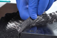
3. De 'overlappende' lagen toevoegen
De 'te grote' lagen worden in de tegenoverliggende zijde van de splitmal gelamineerd, in volgorde.
De eerste laag die wordt toegevoegd, heeft de kleinste (5mm) verlenging, ontworpen om de op maat gesneden eerste laag in de andere zijde van de splitmal enigszins te overlappen. Vervolgens worden de verlengingslagen van 10mm en 15mm toegevoegd.
Terugkerend naar de eerste zijde van de splitmal (waar zich al de op maat gesneden laag in bevindt) worden de twee kortere lagen aan deze helft toegevoegd, wederom in volgorde, waarbij ze geleidelijk korter worden om overeen te komen met de geleidelijk langere overlappingen aan de verlengingszijde.
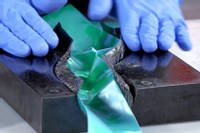
4. De buisvormige bagging film toevoegen
De vacuümzakconfiguratie in deze tutorial is een interne buisvormige vacuümzak. Dit houdt in dat er een lengte buisvormige zak door het midden van de buisvormige splitmal wordt geleid en deze buis vervolgens wordt verbonden met een externe 'enveloppe'-zak aan de buitenkant van de mal.
Het type buisvormige bagging film dat we gebruiken, is onze VB155 zelflossende, gevouwen buisvormige bagging film met een breedte van 100mm.
Met de buisvormige bagging film aan de binnenkant worden de twee helften van de mal voorzichtig samengebracht, waarbij erop wordt gelet dat de 'laps' correct gepositioneerd zijn en niet worden opgevouwen of bekneld wanneer de mal wordt gesloten.
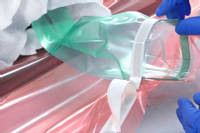
5. De vacuümzak voltooien
Om te beginnen wordt de buitenkant van de splitmal omwikkeld met BR180 ademende doek om een luchtstroompad te bieden en te voorkomen dat de vacuümzak per ongeluk wordt doorboord door scherpe details op de mal.
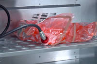
Vervolgens wordt de hele mal omgeven door een grote 'envelop' zak van VB160 vacuümzakfolie. Het principe is dat de buisvormige vacuümzak een 'tunnel' door het midden van de envelopzak creëert. Wanneer het vacuüm wordt getrokken, wordt het van binnenuit de envelopzak getrokken, waardoor de zak op de buitenkant van de mal wordt gezogen en de buisvormige zak op de binnenkant van de buis.
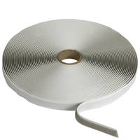
Om deze 'tunnel' door de zak te creëren, wordt de buitenkant van de buisvormige zak afgedicht aan de binnenkant van de envelopzak met behulp van vacuümzak afdichtingstape.
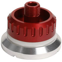
Vervolgens wordt er een volledig vacuüm op de vacuümzak getrokken met behulp van onze EC.4 composiet vacuümpomp. Er wordt zorgvuldig gecontroleerd of de vacuümzak perfect is afgesloten en geen lekken vertoont.
6. Bak de prepreg in de oven
Het vacuüm verpakte onderdeel wordt vervolgens overgebracht naar een oven om uit te harden. Omdat we de XPREG XC110 out-of-autoclave prepreg gebruiken om dit onderdeel te maken, moet een specifieke uithardingscyclus worden gevolgd om de beste resultaten te krijgen. Zie de XC110 verwerkingshandleiding voor volledige details over aanbevolen uithardingscycli en verwerking voor XPREG XC110.
DISCUSSIE (19)
Deel al uw vragen of opmerkingen over deze videohandleiding.
De milieu-impact van composieten is iets genuanceerder dan simpelweg kijken naar een aantal plastic verbruiksartikelen die in het productieproces worden gebruikt. Over het algemeen wordt geavanceerde composiet nu beschouwd als zeer belangrijk voor de productie van lichtere, efficiëntere technologie, vooral in transport. Als u een meter of twee bagging film moet gebruiken om een kilogram van het gewicht van een vliegtuigdeurcomponent te besparen, dan zou de vermindering van de benodigde brandstof gedurende de levensduur van het component de milieu-impact van de films en het productieproces dat wordt gebruikt om het component te maken, overtreffen. Geavanceerde composieten besparen nu al duizenden tonnen CO2 per jaar in passagiersvliegtuigen en andere toepassingen voor massavervoer. Op een verantwoorde manier afgevoerd, veroorzaakt plastic folie geen schade aan het milieu, maar het lichtgewicht component helpt de klimaatverandering gedurende zijn hele levensduur te verminderen.
EEN OPMERKING OF VRAAG ACHTERLATEN
PRODUCTEN DIE IN DIT PROJECT ZIJN GEBRUIKT
Hoewel het niet per se een uitputtende lijst is, werden de volgende gereedschappen en materialen, geleverd door Easy Composites, in dit project gebruikt.
De hieronder getoonde hoeveelheid is de geschatte hoeveelheid die in het project is gebruikt, afgerond naar de dichtstbijzijnde beschikbare kitgrootte of hoeveelheid.
VERSTERKINGEN
GEREEDSCHAP & APPARATUUR
VACUÜMZAKBENODIGDHEDEN
DISCUSSIE (19)
Deel al uw vragen of opmerkingen over deze videohandleiding.
De milieu-impact van composieten is iets genuanceerder dan simpelweg kijken naar een aantal plastic verbruiksartikelen die in het productieproces worden gebruikt. Over het algemeen wordt geavanceerde composiet nu beschouwd als zeer belangrijk voor de productie van lichtere, efficiëntere technologie, vooral in transport. Als u een meter of twee bagging film moet gebruiken om een kilogram van het gewicht van een vliegtuigdeurcomponent te besparen, dan zou de vermindering van de benodigde brandstof gedurende de levensduur van het component de milieu-impact van de films en het productieproces dat wordt gebruikt om het component te maken, overtreffen. Geavanceerde composieten besparen nu al duizenden tonnen CO2 per jaar in passagiersvliegtuigen en andere toepassingen voor massavervoer. Op een verantwoorde manier afgevoerd, veroorzaakt plastic folie geen schade aan het milieu, maar het lichtgewicht component helpt de klimaatverandering gedurende zijn hele levensduur te verminderen.
EEN OPMERKING OF VRAAG ACHTERLATEN
100% VEILIG
BETAALMETHODEN
Easy Composites EU B.V., geregistreerd in Nederland 73601195. Alle inhoud auteursrecht (C) Easy Composites Ltd, 2025. Alle rechten voorbehouden.