Need any help or advice?![]() +44 (0)1782 454499
+44 (0)1782 454499
VIDEOS IN THIS SERIES
This video is part 1 of a 3 part series: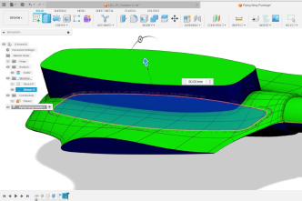
PRODUCTS USED IN THIS PROJECT
Although not necessarily an exhaustive list, the following tools and materials, supplied by Easy Composites, were used in this project.
The quantity shown below is the approximate amount used in the project rounded up to the nearest available kit size or quantity.
MOULD MAKING MATERIALS
PATTERN MAKING MATERIALS

VIDEO TUTORIAL
Practical CAD Techniques for Composite Pattern/Mould Design
In depth video tutorial from Easy Composites covering the design principles and practical CAD techniques required when preparing 3D models for CNC machining into composite patterns. The tutorial uses Autodesk Fusion 360, although the tools and processes are generic and would apply equally to any other engineering CAD package such as Catia, Solidworks or Onshape.
The tutorial begins by looking at the more basic steps of checking draft angles, adding trim allowance, closing apertures, creating flanges and setting up the stock material.
The second half of the tutorial looks at a more complex ‘split-mould’ and covers the process of using draft analysis to create the optimum parting line, as well as design-in features such split-mould clamping bushes.
INTRODUCTION

Introduction
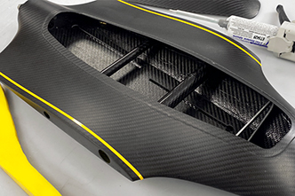
In this tutorial, two parts will be covered - a single engine cover and a more complex UAV fuselage. The Engine cover will enable us to describe the basic features needed for a composite pattern/mould and how we can create them using CAD. The UAV fuselage will build on those basic skills and apply them to a split mould including the additional considerations that will bring - including considerations on creating the split mould and also the use of inserts and other features.
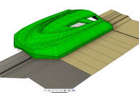
On this first part, We have placed it into the mould to highlight the features on the mould that you cannot see on the part. Firstly this includes open areas that have been blanked off, then you will see a slight extension on the part called the "Trim Allowance" - which allows the part to be made slightly oversize so it can be trimmed precisely. Then the main difference is the addition of the mould flanges which both help release the part and also stiffen the mould - especially if a return is added.
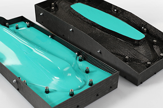
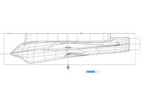
The second part, the fuselage, uses a more complex split mould with a sweeping split line. The use of inserts is utilised to enable the two mould halves to be accurately aligned and bolted together. The nature of the wing root area necessitates the use of vertical flanges and hence the need for the loose shuttering due to lack of draught angle.
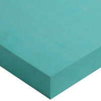
The Patterns have been produced using our EB700 High Temperature Tooling Board, cut using a 3 axis CNC machine and then finished and sealed using our S120 Advanced Board Sealer.The moulds themselves have been manufactured using our XT135 Tooling pre-pregs and the final parts using our XC110 Out of Autoclave Pre-pregs.
TUTORIAL BREAKDOWN
1. CAD Packages and Features
This is not a dedicated CAD tutorial and focused more on its use for composites, so does assume some basic CAD knowledge. For most packages there are tutorial videos and guides on their use which you may find useful if starting from scratch to learn the basics. For this tutorial, we are using the Fusion 360 package, however, even if you are using other packages, often similar functioning tools will be available meaning you can generate the same workflow and end results.
It is worth noting that many CAD packages may have add on functions and tools for mould making and creating parting lines. However, most of these tools are designed and orientated towards injection mould tooling, meaning that their usefulness may well be limited for composites applications. However, if these tools are available to you, it may be worth experimenting with them to gain insights and possible shortcuts that may work for your application.
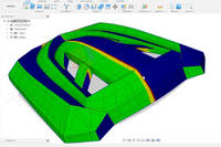
2. Draft Analysis
To ensure there are no release issues, it is important to consider and ensure there is an appropriate draft angle on the tool. To check this in CAD, we will be using a Draft Analysis tool which will analyse the model and display areas that may be of concern. The tool is used in the direction the part will be released from the mould, in this case usually the Z axis.
Ideally for most composites applications, a draft angle greater than 3 degrees will work well. For this part, the settings are set to 0.5 degrees with a 2.5 degree tolerance. The tool will highlight problem areas in red, less than ideal areas in yellow and safe areas in Green.
In this case, the model shape is such that there are no draft angle issues as the draft angle is generous all round. It is worth noting that the part orientation is not level, so it is worth correcting that at this stage as it will help reduce material wastage and machining time when it comes to machining the patterns.
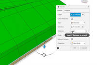
3. Creating Trim Allowance
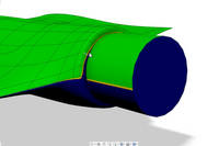
The first feature to be created is a trim allowance. The model is the exact size of the finished part. Adding a Trim Allowance allows the fibre to extend beyond the edge of the part so that when trimmed, the carbon can be cut accurately to the designed edge. This is normally done with the same tangency as the part so that the fabric does not have to bend over tight corners.
To create this feature, the edge of the part is selected and then create a ruled surface setting the type to direction and the Z axis for the direction of the feature. In this case 5mm is set as the Trim Allowance, Typically 5-10mm is sufficient for most pre-preg applications. You may need a bigger Trim allowance for resin infusion. The feature then has a 5 degree kick added on both to aid release of the part from the mould and to leave a slight witness line on the part to give a visible line to trim to.
4. Creating Mould Flanges
On an almost flat part like this, you could pull the trim allowance down to a flat plane to create flanges, however, this is not ideal for all situations so the following workflow can be used.
To create the flanges, the edges on one side are selected and a ruled surface is created that runs outwards. The direction has to be selected as well as the plane to define the feature. The individual edges are then selected. As this part has symmetry, only one side needs to be selected as the flanges can be mirrored later on.
This is repeated for the back edge and side and then the corners are closed up. This is done by using a sweep of this edge profile along the perpendicular edge. The flanges can then be mirrored onto the other side of the tool.
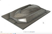
5. Cutting Into Stock
To finish off the pattern, there are only a few more steps needed. Firstly any holes in the part surface can be filled using the patch tool. Then the various features can be stitched together to create one body. A sketch is then used to create the return on the flange and the split body tool used to remove the excess. A ruled edge is now created using this perimeter to create the return and a 5 degree angle is used. Once this has been created, the features are now all complete and the surfaces can be stitched together again.
The stock material is then drawn in and given a size of at least 10mm bigger on the sides and 5mm on the bottom. The stock is then split using the surfaces created above. The unwanted side can be hidden and then some generous fillets are created in the corners and the return edge extended for better machining access. The work on this pattern is now done and the tool paths can be generated and the pattern machined by CNC.
6. Split Mould Parting Line and Faces
The complexity of this fuselage model means that we will need a split mould to make it effectively. The first feature to create is the aperture flange where the motor would mount. This needs to be done first as it is going to be on the parting line of the split mould. First a face is created using 3 points in the aperture, then a circle can be sketched, then selected and used to extrude the feature.
The model is then orientated so that the parting line can be analysed and created. The draft analysis tool can then be used and the model inspected to find the best parting line for the tool. Where there is a tight area on the parting line, the model angle can be adjusted to see if that would improve the situation. In this case, rotating the model 3.75 degrees removes the issue and means that the parting line can be created without any risk of undercuts causing problems later on.
The next feature to create is the aperture flange around the rebated hatch area. Firstly the sketch tool is used to highlight the edge of the aperture and then and offset used to create the rebate and some trim allowance. The edge of this offset can then be extruded vertically with a 5 degree draught angle to finish the aperture flange.
To draw the parting line, we recommend doing it manually. Some CAD packages can draw the line for you, but often the line created will need to be adjusted to suit so often creating it manually is the quickest option by closely following the parting line from the draft analysis. A surface is then extruded from this drawn parting line profile to create the parting faces.
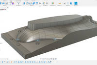
7. Stock Material Cutting
Now we want to model the stock material that we want to cut. First of all we will sketch a rectangle around the model extending flush to the two sides (because of the shuttering) and extending a set distance on the other sides. Once that rectangle is drawn, we can use it to extrude and create the stock just big enough to encapsulate the model completely.
The stock now needs to be split into the two halves. This is done by using the split body tool and using the flange surface as the cutting tool. To create the tool cavities, the combine tool is used selecting the model to cut and one of the stock pieces. This is repeated for the other stock and once complete, the full mould cavity is now modelled onto the stock material.
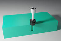
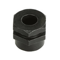
8. Mould Alignment with Clamping Bushes
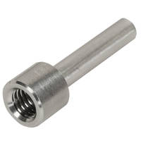
To ensure both halves of the tool maintain proper alignment in use, Mould Clamping Bushes are used, These consist of the metal bush and alignment dowel pin. These work by being precisely located onto the pattern using a drilled hole. The bush can then be laminated around as the tool is laid up, Once cured, the dowel pin can be extracted leaving a perfectly aligned and hard wearing bolt location for tool alignment.
As we are using a 3 axis CNC machine, the alignment holes will be drilled vertically. This means that a flat perpendicular plane is sat under the bush to ensure proper alignment. This looks like flat plateaus on any of the angled sections of the mould. Perfectly flat areas do not need additional work
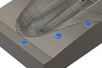
9. Drawing the Bush Locating Pads
To draw the locating pads, first a sketch is created to draw the locating pin holes. In this case the holes will need to be 6.1mm in diameter. This is to enable a snug fit on the locating dowel pins when inserting them into the pattern. Depending on the dowels you are using, machining strategy and material, you may want to experiment on some scrap material to find the optimal hole size for the best fit. In this case, 6.1mm has been found to be the ideal size. An additional 18mm circle is then sketched which will be used for the flat locating plateau itself.
Placement of the bushes does not need to be that precise and can be drawn by hand. Typically you want them between 20 and 25mm from the edge of the mould surface to ensure the surface is clamped tightly. Spacing on a part like this between 75 and 100mm spacing is fine. These are being drawn on only one side at present as they can be mirrored at a later stage.
Using the sketch, the pads can be extruded. The offset and height can be adjusted to minimise the overall size of the pad as it only needs to be big enough to provide the flat surface. A draft angle of 30 degrees is used to ensure there are no issues with them locking into the moulds. The join feature is used to make them into one body. This is then repeated for the other locating pads. The work is then mirrored to create the other pads on the other side of this tool. The pads are created on the other mould by using the cut tool to cut the locating pads into the other mould half.
Having created the pads on both tool halves, they are size on size which could cause some interference issues depending on machining tolerances. So the push pull tool is used to create a 0.5mm offset on the female side so that there is enough slack.
10. Creating the Pattern
So far, the model that we have created is of the mould itself, so it needs to be reversed to make the actual patterns. This uses a similar process for creating stock as before. We can extrude through the model by selecting the base and extruding upwards. The combine tool is then used to cut the pattern from the stock using the mould as the cutting tool. This process can be repeated to create the other half of the pattern.
The final step is to create the bores for the dowel pins for the moulds. This is created by using the previous sketch to extrude the holes into both the pattern halves. That is the patterns now created. It is important to note that these particular patterns will be using shuttering on the edge to create the mould return flanges. These features could be machined into the pattern, but without a draft angle the mould would be very difficult to demould. The shuttering is simply some carbon fibre flat sheeting bolted onto the side of the pattern and can be simply unbolted to aid the demoulding of the mould.
The design side of the patterns are now complete and these pattern models can be used to create the necessary tool paths for CNC cutting them out of tooling board. The stock block can then be prepared, cutting and bonding the blocks together prior to machining. A pattern of this size will take several stages to cut using different tools. The CNC machined pattern can then be hand finished and sealed prior to being used to create the mould. In this case we are using the XT135 Tooling pre-preg which is laid onto the pattern, cured, finished and then release coated making the moulds ready for service.
DISCUSSION (11)
Please share any questions or comments you may have about this video tutorial.
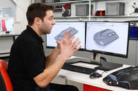
It is known as a "Space mouse" and there are a few different models.
Plastic injection moulding is not a composite process at this level yet. Resin infusion and resin transfer moulding processes do exist albeit they are slightly different in both the approach and technique. There are some overlap with some composite processes, eg infusion uses vacuum in a bag to draw resin into the mould. Forged carbon fibre is a compression moulding process between 2 tools. So there is some cross over in some areas albeit there is not injection moulding in the traditional plastics sense.
Commonly it is for high temperature applications such as pre-preg. The thermal expansion of the mould is then almost identical to the expansion of the materials being used in it which can be advantageous in some situations. Machined moulds from tooling board generally have a limited lifespan and billet metal machined tools can be very expensive to produce both in material and machining costs.
Thanks for your comment. In this case with this model and Fusion, we found this method worked best without causing any geometry issues or the tool failing to work correctly. Other models and other CAD packages may work in a more simple way.
Good question, it really depends on the geometry of the model you're working from, I find that tangent surfaces can often result in bad geometry around complex edges, but that said give it a try and if the results look good then it's fine, there's no exact science to creating a trim allowance.
While it is possible to do this for prototypes and one-offs the reason that you would make a mould from a pattern is that you want the mould to have the same CTE (thermal expansion) rate as the part you are making, so for these carbon fibre parts you want a carbon fibre mould. Another advantage it that you can quickly make more moulds from a pattern for volume production.
The most affordable way is to spend an hour a day learning it through tutorials for about a month or two, aside from that, approach students from a local engineering college, you might get quite a lot done for some beer money!
The engine cover we will laminate in a future video, the component itself is something we’ve made for another YouTube channel (V8Creative). The fuselage will feature next in a video about the machining of the pattern and laminating the mould. No current plans on laminating the fuselage but you never know.
It depends how precise and relevant that is for your specific application, but most CAD packages have a relatively simple scaling function should you need to do this.
For low volume applications, prototyping etc, you certainly can use the EB700 Epoxy Tooling block as a mould. However, in general and for most uses, a proper composite mould, as shown, offers better durability and finish for the tooling.
Some CAD packages will have advanced composite tools within them, or available to buy, to help with some part of the design process. The same goes with FEA tools to help you analyse the design. Similar with ply template and cutting tools.
LEAVE A COMMENT OR QUESTION
PRODUCTS USED IN THIS PROJECT
Although not necessarily an exhaustive list, the following tools and materials, supplied by Easy Composites, were used in this project.
The quantity shown below is the approximate amount used in the project rounded up to the nearest available kit size or quantity.
MOULD MAKING MATERIALS
PATTERN MAKING MATERIALS
DISCUSSION (11)
Please share any questions or comments you may have about this video tutorial.
It is known as a "Space mouse" and there are a few different models.
Plastic injection moulding is not a composite process at this level yet. Resin infusion and resin transfer moulding processes do exist albeit they are slightly different in both the approach and technique. There are some overlap with some composite processes, eg infusion uses vacuum in a bag to draw resin into the mould. Forged carbon fibre is a compression moulding process between 2 tools. So there is some cross over in some areas albeit there is not injection moulding in the traditional plastics sense.
Commonly it is for high temperature applications such as pre-preg. The thermal expansion of the mould is then almost identical to the expansion of the materials being used in it which can be advantageous in some situations. Machined moulds from tooling board generally have a limited lifespan and billet metal machined tools can be very expensive to produce both in material and machining costs.
Thanks for your comment. In this case with this model and Fusion, we found this method worked best without causing any geometry issues or the tool failing to work correctly. Other models and other CAD packages may work in a more simple way.
Good question, it really depends on the geometry of the model you're working from, I find that tangent surfaces can often result in bad geometry around complex edges, but that said give it a try and if the results look good then it's fine, there's no exact science to creating a trim allowance.
While it is possible to do this for prototypes and one-offs the reason that you would make a mould from a pattern is that you want the mould to have the same CTE (thermal expansion) rate as the part you are making, so for these carbon fibre parts you want a carbon fibre mould. Another advantage it that you can quickly make more moulds from a pattern for volume production.
The most affordable way is to spend an hour a day learning it through tutorials for about a month or two, aside from that, approach students from a local engineering college, you might get quite a lot done for some beer money!
The engine cover we will laminate in a future video, the component itself is something we’ve made for another YouTube channel (V8Creative). The fuselage will feature next in a video about the machining of the pattern and laminating the mould. No current plans on laminating the fuselage but you never know.
It depends how precise and relevant that is for your specific application, but most CAD packages have a relatively simple scaling function should you need to do this.
For low volume applications, prototyping etc, you certainly can use the EB700 Epoxy Tooling block as a mould. However, in general and for most uses, a proper composite mould, as shown, offers better durability and finish for the tooling.
Some CAD packages will have advanced composite tools within them, or available to buy, to help with some part of the design process. The same goes with FEA tools to help you analyse the design. Similar with ply template and cutting tools.
LEAVE A COMMENT OR QUESTION
100% SECURE
PAYMENT METHODS
Easy Composites EU B.V., registered in the Netherlands 73601195. All content copyright (C) Easy Composites Ltd, 2025. All rights reserved.