Hulp of advies nodig?![]() +44 (0)1782 454499
+44 (0)1782 454499
VIDEO'S IN DEZE SERIE
Deze video is deel 1 van een 4-delige serie: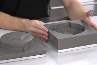
PRODUCTEN DIE IN DIT PROJECT ZIJN GEBRUIKT
Hoewel het niet per se een uitputtende lijst is, werden de volgende gereedschappen en materialen, geleverd door Easy Composites, in dit project gebruikt.
De hieronder getoonde hoeveelheid is de geschatte hoeveelheid die in het project is gebruikt, afgerond naar de dichtstbijzijnde beschikbare kitgrootte of hoeveelheid.
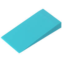
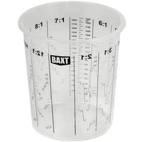
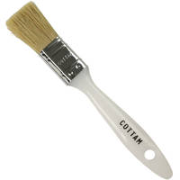
HULPMATERIALEN
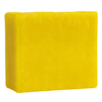
MATERIALEN VOOR HET MAKEN VAN MALLEN
VIDEO-HANDLEIDING
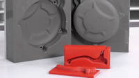
Een Tweedelige Compressiemal Gieten voor Gesmeed Koolstof
WAT U GAAT LEREN
In deze video-tutorial laten we zien hoe je tweedelige aangepaste mallen of compressiemallen maakt die kunnen worden gebruikt om gesmede koolstofvezel componenten te produceren met behulp van een compressie vormproces.
- Voor welke processen is een 'aangepaste' compressiemal geschikt?
- Overwegingen voor de productie van de mal
- Positionering en uitbreiding van het patroon met behulp van plasticine
- Het gieten van de binnen- en buitenmal met behulp van TC80 Tool Cast aluminium gevulde epoxy giethars
INTRODUCTIE
Introductie
Gesmeed koolstofvezel is de term die is aangenomen om korte of ‘gehakte’ strengen koolstofvezel te beschrijven die in een meerdelige mal worden geperst om sterke, solide geometrieën te creëren die niet praktisch zouden zijn met conventionele composietprocessen.
Compressiemal gereedschappen bestaan uit 2 of meer delen die samenkomen en een holte achterlaten waar het onderdeel wordt gevormd. In bijna alle gevallen zal de mal een ‘blok’-achtige vorm hebben om sterkte te bieden en het klem- of compressieproces praktisch te maken.
De belangrijkste overweging bij het ontwerpen van gereedschap voor dit proces is het opnemen van een telescopisch gedeelte waarbij het mannelijke gereedschap als een zuiger in een cilinder fungeert tijdens het sluiten. Dit biedt ruimte om de niet-samengeperste vezel te laden en tijdens het sluiten wordt overtollige hars door de scheidingslijn geperst, maar omdat deze zeer nauwsluitend is, kan de vezel niet ontsnappen, waardoor u de juiste vezel-harsverhouding overhoudt. Dit telescopische of ‘zuigerachtige’ element moet diep genoeg zijn om de mal te laten sluiten voordat de vezel wordt verstoord. De exacte grootte van deze functie is afhankelijk van de vorm en het ontwerp van de mal, maar een algemene regel dat de functie minstens 25% van de diepte van het uiteindelijke onderdeel beslaat, zou een goede schatting zijn. In het geval van een tweedelige mal vereist deze functie een lichte lossingshoek van 2-3 graden om de mal gemakkelijk te kunnen scheiden. Bij meerdelig gereedschap is het vaak mogelijk om de mal zo te ontwerpen dat deze kan worden gescheiden van een volledig parallelle ‘zuiger’-functie.
WAT U NODIG HEEFT
Materialen en Apparatuur die Nodig Zijn voor de Compressiemal
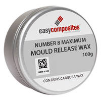
RW4 Lossingsmiddel
RW4 hoogwaardige spuitlossingswas is het aanbevolen lossingssysteem voor compressiemoulding bij omgevingstemperatuur. Dit lossingsmiddel presteert bijzonder goed bij het lossen van stijve gietstukken en mallen van elkaar, omdat het een dikke barrière vormt die relatief zacht is en daardoor indien nodig een beetje kan bewegen tijdens het lossen.
Ontmollingswas
Traditionele ontmollingswas die wordt gebruikt om het originele onderdeel te coaten, zodat de giethars er niet aan blijft plakken.
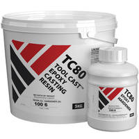
TC80 ToolCast Epoxy Giet hars
TC80 is een epoxy giethars ontworpen voor het gieten van een breed scala aan gereedschappen. In dit specifieke geval is het ideaal voor gebruik bij het maken van kleine tot middelgrote compressiegereedschappen voor gebruik in het gesmede koolstofvezelproces
Plasticine
Plasticine is ideaal voor het verlengen van elk model om de noodzakelijke telescopische sectie te creëren, wat essentieel is om de initiële compressie van de twee malhelften mogelijk te maken. Het is stevig genoeg om zijn vorm te behouden tijdens het gieten van de hars, maar kan toch gemakkelijk met de hand worden gevormd en gladgestreken. Bovendien kan het worden hergebruikt zodra de mal klaar is.
Vulwas
Vulwas en/of plasticine is vaak nuttig voor het afdichten van schroefdraden op malbouten of om uitwerpgaten in de mal op te vullen en af te dichten.
Polypropyleen Plaat
Ideaal voor het maken van malbodemplaten, zijkanten en flenzen. Kan eenvoudig op maat worden gesneden en gelijmd met smeltlijm. Hecht van nature niet aan de meeste harssystemen, wat betekent dat het zonder lossingsmiddelen van de afgewerkte mal kan worden afgepeld.
PROJECTSPECIFICATIE
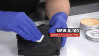
1. Losmiddel Anbrengen op het Originele Onderdeel
Het originele onderdeel moet worden voorzien van een losmiddel om te voorkomen dat de hars aan het onderdeel blijft plakken tijdens het uitharden. Breng 5 lagen was als lossingsmiddel aan op het onderdeel en zorg ervoor dat het hele onderdeel bedekt is. Breng elke laag aan en poets deze vervolgens voorzichtig uit. Wacht 15 minuten tussen elke laag.
2. Gaten of ongewenste details opvullen
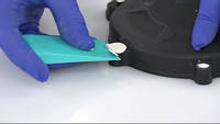
Gebruik plasticine om eventuele gaten of ongewenste details op het uiteindelijke onderdeel op te vullen. De gaten op de afdekking zijn gemakkelijker uit te boren tijdens de nabewerking, dus in dit geval zijn ze gevuld met plasticine. De lossingswiggen trimmen de plasticine gemakkelijk en snel om een nette afwerking te geven aan het gevulde gat zonder krassen op het plastic.
3. Perimeteruitbreiding Creëren
Het is essentieel om een perimeteruitbreiding toe te voegen waarbij het mannelijke gereedschap als een zuiger in een cilinder fungeert tijdens het sluiten. Dit biedt ruimte om de niet-samengeperste vezel te laden, waarna tijdens het sluiten overtollige hars door de scheidingslijn wordt geperst.
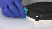
Allereerst wordt een grondplaat gesneden uit polypropyleenplaat, wat een ideaal oppervlak is voor het vormproces. Er wordt een grote hoeveelheid plasticine gebruikt om de perimeteruitbreiding rond de basis van het onderdeel te creëren. Denk eraan om bij het trimmen van de plasticine een lossingshoek van 3 tot 5 graden aan te houden om zowel het compressieproces als het lossen aan het einde te vergemakkelijken.
Er wordt een laatste laag was als lossingsmiddel aangebracht om ervoor te zorgen dat het oppervlak glad is en dat de afgewerkte mal gemakkelijk loslaat.
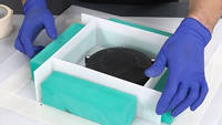
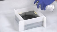
4. De Maldoos Maken
Polypropyleen wordt gebruikt omdat het van nature loslaat van de hars zodra deze is uitgehard. Snijd stroken van de plaat om randen voor de mal te maken. Eenmaal uitgelijnd, worden de platen met smeltlijm op hun plaats gelijmd voordat ze worden afgedicht met de smeltlijm. Het is essentieel dat de doos volledig is afgesloten, zodat de hars er niet uit kan lekken. Blokken hout of soortgelijk materiaal worden vervolgens aan de buitenkant van de maldoos bevestigd om extra steun en stevigheid te bieden.
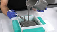
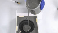
5. De eerste helft van de Compressiemal Gieten
De TC80 ToolCast is ideaal voor deze toepassing vanwege het gebruiksgemak en de robuuste aard. Meet de juiste hoeveelheid hars en harder af in een mengbeker. Meng grondig gedurende 2-3 minuten en schraap de zijkanten en de bodem van de beker. Giet in een schone beker en meng nogmaals 2-3 minuten.
Breng eerst een laag van de TC80 ToolCast aan op het oppervlak van het onderdeel om de oppervlaktespanning te breken en ervoor te zorgen dat er geen holtes of luchtbellen in de hars op het oppervlak van de mal ontstaan. Vul vervolgens de rest op met de rest van de hars. Laat de hars minimaal 24 uur bij 20°C uitharden voordat u probeert te lossen.
6. Lossen en Voorbereiden voor het Tweede Gietsel
Nu de hars volledig is uitgehard, kunnen we de barrières en de grondplaat verwijderen. Bewaar de barrières, want deze worden later hergebruikt. Draai de mal om en schraap de plasticine van de onderkant, waarbij u ervoor zorgt dat u het originele onderdeel niet verwijdert of lost. Het originele onderdeel moet in de mal blijven zitten om de holte voor het compressievormproces te creëren. Zodra het meeste van de plasticine is verwijderd, gebruikt u een dunne laag was als lossingsmiddel om eventuele laatste resten te verwijderen.
Vul gaten opnieuw en herstel ze om ervoor te zorgen dat ze nog steeds zijn afgedicht met de plasticine voor het volgende gietsel. Eventuele ongewenste details kunnen op dezelfde manier met plasticine aan deze kant worden opgevuld. Om het lossen te vergemakkelijken, is het verstandig om wiglocaties te creëren. Maak een wigvorm met plasticine en trim en vorm deze met een lossingswig. Dit helpt bij het lossen, omdat het dan mogelijk is om een lossingswig in de bijpassende uitsparing te drijven.
De barrières van eerder worden vervolgens hergebruikt om barrières voor het tweede gietsel te creëren. Dubbelzijdige tape wordt vervolgens gebruikt om ze op hun plaats te bevestigen en, net als voorheen, wordt smeltlijm gebruikt om de barrières aan de buitenkant volledig af te dichten om de mal een nettere afwerking te geven. Breng vervolgens met fileerwas voorzichtig een rand aan rond de binnenrand van de maldoos om ervoor te zorgen dat er een afdichting is tussen de barrières en de hars.
De mal moet vervolgens worden besproeid met de RW4 Spray release agent. Het bouwt een dikke maar enigszins flexibele laag op die helpt bij het lossen. Doorgaans worden 3 tot 4 lagen gebruikt in deze toepassing. Het wordt niet gebruikt op de A-kant van de mal, omdat het een lichte textuur achterlaat, maar dit is geen probleem aan de achterkant van het onderdeel, die niet zichtbaar is wanneer het is gemonteerd.
7. De Tweede Helft van de Mal Gieten
Het gieten van de TC80 ToolCast-hars is een identiek proces aan de eerste helft van de mal. Meet de juiste hoeveelheid hars en harder af in een mengbeker. Meng grondig gedurende 2-3 minuten en schraap de zijkanten en de bodem van de beker. Giet in een schone beker en meng nogmaals 2-3 minuten.
Breng eerst een laag van de TC80 ToolCast aan op het oppervlak van het onderdeel om de oppervlaktespanning te breken en ervoor te zorgen dat er geen holtes of luchtbellen in de hars op het oppervlak van de mal ontstaan. Vul vervolgens de rest op met de rest van de hars. Laat de hars minimaal 24 uur bij 20°C uitharden voordat u probeert te lossen.
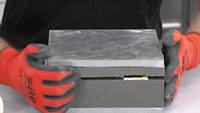
8. De Compressiemal Ontvormen en Afwerken
Nu de TC80 ToolCast-hars volledig is uitgehard, kunt u beginnen met het ontvormen. De polypropyleen barrières moeten gemakkelijk verwijderd kunnen worden, waardoor de tweedelige massieve blokmal overblijft. In dit stadium wordt de mal verstevigd voordat deze wordt gescheiden en ontvormd.
Om de mal sterker te maken en scheuren tijdens het ontvormen te voorkomen, wordt een legeringsplaat op elke helft gelijmd. De te verlijmen oppervlakken worden zwaar opgeschuurd met een Perma-Grit schuurblok en vervolgens gereinigd. Onze VM100 zwarte methylmethacrylaatlijm wordt gebruikt om de legeringsplaten aan beide zijden van de mal te lijmen en vervolgens te laten uitharden.
Zodra de lijm is uitgehard, worden ontvormwiggen in de ontvormspleten gestoken en gebruikt om de 2 helften van de mal langzaam te scheiden. Er wordt op gelet dat de scheiding aan elke kant gelijkmatig gebeurt om te voorkomen dat de twee helften van de mal tegen elkaar en het onderdeel in het midden klem komen te zitten. Zodra de opening mooi is, moet het mogelijk zijn om de 2 helften van de mal met de hand te scheiden.
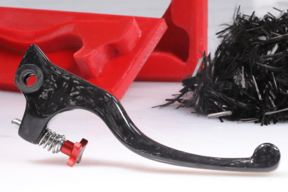
Wrik voorzichtig aan de randen van het onderdeel om het van de wand van de mal los te maken, werk het onderdeel voorzichtig uit de mal en verwijder het vervolgens uit de mal. Verwijder alle resten van was en plasticine en verwijder eventuele bramen of ruwe randen op de mal. Reinig de mal grondig voor gebruik. De tweedelige compressiemal is nu klaar om te worden gebruikt om een gesmeed carbon onderdeel te maken.
DISCUSSIE (13)
Deel al uw vragen of opmerkingen over deze videohandleiding.
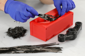
Hoewel het mogelijk is om meer continue vezelformaten van carbonversterking, zoals een geweven doek, te compressiegieten, zult u merken dat geweven versterkingen veel beperkender zijn in termen van de vormen die u met succes kunt gieten.
De reden dat dit proces zo goed werkt met gehakt koolstofvezel touw is omdat de individuele, korte strengen koolstofvezel redelijk vrij kunnen bewegen en zich onder druk in de mal kunnen verdelen. Als u een geweven doek gebruikt, zijn de vezels continu en overbruggen ze het oppervlak van het onderdeel, naarmate u druk toevoegt, begint het de wapening op zijn plaats te vergrendelen en kan deze zich niet herverdelen in hoeken, holtes, details enz. Het resultaat, als u een onderdeel zoals dit vliegwieldeksel zou maken, is voiding/bridging in verschillende delen van het onderdeel. Echter, voor onderdelen die overwegend vlak zijn of slechts lichte contouren hebben, kunt u wellicht wegkomen met een geweven wapening. Een optie zou een hybride aanpak kunnen zijn waarbij u geweven doek op het oppervlak gebruikt en dit vervolgens ondersteunt met gehakt touw, waardoor u effectief het beste van beide werelden krijgt. Nogmaals, het zou afhangen van de geometrie van het onderdeel dat u maakt.
Dit telescopische of 'zuigerachtige' element moet diep genoeg zijn om de mal te laten beginnen sluiten voordat de vezel wordt verstoord. De exacte grootte van dit kenmerk is afhankelijk van de vorm en het ontwerp van de mal, maar een algemene regel om het kenmerk minstens 25% van de diepte van het uiteindelijke onderdeel te laten uitsteken, zou een goede schatting zijn. In het geval van een tweedelige mal heeft dit kenmerk een lichte lossingshoek van 2-3 graden nodig om de mal gemakkelijk te kunnen scheiden. In meerdelige tooling is het vaak mogelijk om de mal zo te ontwerpen dat deze kan worden gescheiden van een volledig parallel 'zuiger'-kenmerk.
Er zijn een paar dingen waarmee rekening moet worden gehouden met betrekking tot de geschiktheid van een prepreg voor een compressiegietproces. Ten eerste moeten we het hars systeem zelf beschouwen. Om een prepreg hars systeem geschikt te maken voor gebruik met een tweedelige compressiemal gemaakt met de TC80 Tool Cast hars, moet u ervoor zorgen dat het hars systeem kan worden uitgehard bij een temperatuur binnen de gebruikstemperatuur van de TC80, die 80°C is. Hoewel de aanbevolen uithardingstemperatuur voor onze XPREG component prepregs, XC110 en XC130, 120°C is, kunnen ze beide *initieel* worden uitgehard bij 80°C (de uithardingstijd zal uiteraard langer zijn) en vervolgens worden ontvormd (uit de TC80 mal) voordat ze 'nagehard' worden bij een hogere temperatuur om hun Tg en mechanische eigenschappen te verbeteren.
Met betrekking tot de versteviging zelf, zijn conventionele verstevigingsformaten zoals geweven stof, multiaxiaal en unidirectioneel, niet goed geschikt voor compressie moulding. De reden hiervoor is dat de versteviging in staat moet zijn om 'rond te bewegen' in de mal, waardoor het gebieden van de mal kan bereiken waar minder versteviging is, holtes kan vullen en de dikte van de opening tussen de compressie gereedschappen kan aanpassen. Al deze dingen zijn moeilijk te bereiken voor een continu vezel formaat. In plaats daarvan is een korte streng versteviging vereist, zoals chopped touw of chopped UD prepreg. Op dit moment zijn dergelijke prepregs zeer zeldzaam en we hebben er momenteel geen in het XPREG assortiment, we werken er echter aan en hopen het zeer binnenkort aan ons assortiment toe te voegen.
Inderdaad. In de bijbehorende video (die we hopelijk volgende week uitbrengen) gebruiken we 3D-geprinte mallen, naast deze massief gegoten mal, om de gesmede carbon onderdelen te produceren. Harsprinten is potentieel goed voor het produceren van massieve 3D-prints, maar doet vaak afbreuk aan de maatnauwkeurigheid, zeker in onze ervaring, maar ja, ze leveren wel een betere oppervlakteafwerking op.
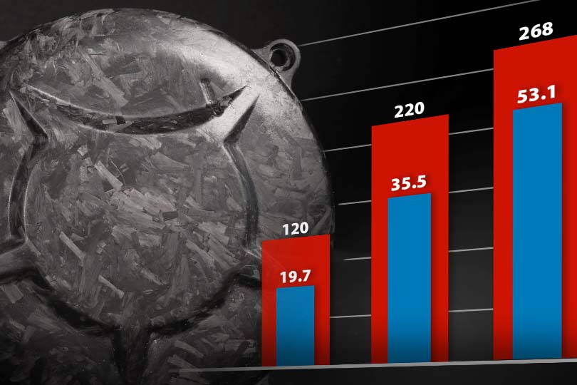
Vooral dankzij Lamborghini betekent de term 'gesmeed' carbon de laatste jaren composietcomponenten die zijn gemaakt met behulp van korte, willekeurig georiënteerde koolstofvezels, gevormd onder druk. Het verschilt van componenten die zijn gelamineerd met meer traditionele vormen van koolstofvezel (d.w.z. geweven koolstofvezeldoek) doordat de kortere koolstofvezels in het laminaat kunnen bewegen, waardoor ze complexere vormvormen onder druk kunnen vullen op een manier die geweven of unidirectionele lange vezels niet kunnen. Het compromis is echter de uiteindelijke sterkte - componenten gemaakt met unidirectionele lange vezels of geweven versteviging zullen sterker zijn en kunnen geoptimaliseerde vezeloriëntatie benutten (d.w.z. vezels uitgelijnd in de richting waar de sterkte het meest nodig is) om componenten met betere mechanische eigenschappen te produceren. Kortom, gesmeed carbon doet concessies aan de sterkte, maar biedt een materiaal dat beter kan 'vloeien' bij compressievormen, wat betekent dat het kan worden gebruikt op een manier die geweven of UD-materialen niet kunnen.
Goede vraag. Wij zijn ook ingenieurs en ze zijn ook belangrijk voor ons, dus we hebben hier intern verschillende gesprekken over gehad voordat we de video maakten! Ik zal proberen een gedetailleerd antwoord te geven over waar we zijn uitgekomen met onze denkwijze:
Allereerst is dit niet onze naam voor het proces, het is een vrij gevestigde manier om compressiegevormde korte koolstofvezels te beschrijven - vooral omdat Lamborghini het 'gesmeed carbon' noemt en het al een paar jaar op grote schaal gebruikt. Het anders noemen zou actieve inspanning vereisen (en betekenen dat veel mensen die geïnteresseerd zijn in 'gesmeed carbon' onze informatie niet vinden).
Ten tweede, over de etymologie van het woord 'gesmeed', zowel in een gevestigde technische context als in de geschiktheid en toepasbaarheid ervan in een composietcontext (ongeacht of Lamborghini en anderen het gebruikten), denken we niet dat het ver van de waarheid afstaat. Hoewel 'gesmeed' iets specifieks betekent in een context van het vormen van metaal, betekent het woord gesmeed ook "gevormd door persen of hameren met of zonder warmte" (Merriam Webster dictionary) of "iets maken of produceren, vooral met enige moeite" (Cambridge dictionary). Aangezien het proces - in deze context - verwijst naar compressievormen onder druk, lijkt deze beschrijving redelijk treffend.
Hoewel je een 'gesmeed' koolstofvezel onderdeel zeker 'compressiegevormd carbon' zou kunnen noemen, zou je de meeste koolstofvezel onderdelen eigenlijk 'compressiegevormd' kunnen noemen, omdat veel processen - vacuümzakken, prepreg, SMC enz., allemaal vormen van compressievormen zijn. Gesmeed carbon is een manier om compressievormen van korte koolstofvezels te onderscheiden van traditionele geweven of lange vezelversteviging. De korte vezels zijn essentieel voor het proces omdat ze de versteviging in staat stellen gemakkelijker te 'vloeien' om zich aan te passen aan de vormcontouren onder druk in een star gereedschap, iets dat niet gebeurt met geweven of lange vezelversteviging (wat leidt tot holtevorming).
Hoewel het vacuümzakken zelf omzeilt, wordt er nog steeds een redelijke hoeveelheid kracht uitgeoefend in de compressiefase, die een deel van de krachten repliceert die betrokken zijn bij vacuümzakken. Dat helpt bij de vezelconsolidatie en het verwijderen van overtollige hars.
Hallo Tom, ja, je kunt RW4 zeker gebruiken in situaties waarin je ook PVA-lossingsmiddel zou overwegen; ze zijn vergelijkbaar in die zin dat ze allebei uiterst betrouwbaar zijn, maar de oppervlakteafwerking enigszins aantasten. In de meeste situaties zal een spray wax zoals RW4 nog betrouwbaarder zijn dan PVA, omdat het wordt aangebracht door te spuiten, het loopt niet het risico op visogen en het missen van gebieden.
EEN OPMERKING OF VRAAG ACHTERLATEN
PRODUCTEN DIE IN DIT PROJECT ZIJN GEBRUIKT
Hoewel het niet per se een uitputtende lijst is, werden de volgende gereedschappen en materialen, geleverd door Easy Composites, in dit project gebruikt.
De hieronder getoonde hoeveelheid is de geschatte hoeveelheid die in het project is gebruikt, afgerond naar de dichtstbijzijnde beschikbare kitgrootte of hoeveelheid.
HULPMATERIALEN
MATERIALEN VOOR HET MAKEN VAN MALLEN
DISCUSSIE (13)
Deel al uw vragen of opmerkingen over deze videohandleiding.
Hoewel het mogelijk is om meer continue vezelformaten van carbonversterking, zoals een geweven doek, te compressiegieten, zult u merken dat geweven versterkingen veel beperkender zijn in termen van de vormen die u met succes kunt gieten.
De reden dat dit proces zo goed werkt met gehakt koolstofvezel touw is omdat de individuele, korte strengen koolstofvezel redelijk vrij kunnen bewegen en zich onder druk in de mal kunnen verdelen. Als u een geweven doek gebruikt, zijn de vezels continu en overbruggen ze het oppervlak van het onderdeel, naarmate u druk toevoegt, begint het de wapening op zijn plaats te vergrendelen en kan deze zich niet herverdelen in hoeken, holtes, details enz. Het resultaat, als u een onderdeel zoals dit vliegwieldeksel zou maken, is voiding/bridging in verschillende delen van het onderdeel. Echter, voor onderdelen die overwegend vlak zijn of slechts lichte contouren hebben, kunt u wellicht wegkomen met een geweven wapening. Een optie zou een hybride aanpak kunnen zijn waarbij u geweven doek op het oppervlak gebruikt en dit vervolgens ondersteunt met gehakt touw, waardoor u effectief het beste van beide werelden krijgt. Nogmaals, het zou afhangen van de geometrie van het onderdeel dat u maakt.
Dit telescopische of 'zuigerachtige' element moet diep genoeg zijn om de mal te laten beginnen sluiten voordat de vezel wordt verstoord. De exacte grootte van dit kenmerk is afhankelijk van de vorm en het ontwerp van de mal, maar een algemene regel om het kenmerk minstens 25% van de diepte van het uiteindelijke onderdeel te laten uitsteken, zou een goede schatting zijn. In het geval van een tweedelige mal heeft dit kenmerk een lichte lossingshoek van 2-3 graden nodig om de mal gemakkelijk te kunnen scheiden. In meerdelige tooling is het vaak mogelijk om de mal zo te ontwerpen dat deze kan worden gescheiden van een volledig parallel 'zuiger'-kenmerk.
Er zijn een paar dingen waarmee rekening moet worden gehouden met betrekking tot de geschiktheid van een prepreg voor een compressiegietproces. Ten eerste moeten we het hars systeem zelf beschouwen. Om een prepreg hars systeem geschikt te maken voor gebruik met een tweedelige compressiemal gemaakt met de TC80 Tool Cast hars, moet u ervoor zorgen dat het hars systeem kan worden uitgehard bij een temperatuur binnen de gebruikstemperatuur van de TC80, die 80°C is. Hoewel de aanbevolen uithardingstemperatuur voor onze XPREG component prepregs, XC110 en XC130, 120°C is, kunnen ze beide *initieel* worden uitgehard bij 80°C (de uithardingstijd zal uiteraard langer zijn) en vervolgens worden ontvormd (uit de TC80 mal) voordat ze 'nagehard' worden bij een hogere temperatuur om hun Tg en mechanische eigenschappen te verbeteren.
Met betrekking tot de versteviging zelf, zijn conventionele verstevigingsformaten zoals geweven stof, multiaxiaal en unidirectioneel, niet goed geschikt voor compressie moulding. De reden hiervoor is dat de versteviging in staat moet zijn om 'rond te bewegen' in de mal, waardoor het gebieden van de mal kan bereiken waar minder versteviging is, holtes kan vullen en de dikte van de opening tussen de compressie gereedschappen kan aanpassen. Al deze dingen zijn moeilijk te bereiken voor een continu vezel formaat. In plaats daarvan is een korte streng versteviging vereist, zoals chopped touw of chopped UD prepreg. Op dit moment zijn dergelijke prepregs zeer zeldzaam en we hebben er momenteel geen in het XPREG assortiment, we werken er echter aan en hopen het zeer binnenkort aan ons assortiment toe te voegen.
Inderdaad. In de bijbehorende video (die we hopelijk volgende week uitbrengen) gebruiken we 3D-geprinte mallen, naast deze massief gegoten mal, om de gesmede carbon onderdelen te produceren. Harsprinten is potentieel goed voor het produceren van massieve 3D-prints, maar doet vaak afbreuk aan de maatnauwkeurigheid, zeker in onze ervaring, maar ja, ze leveren wel een betere oppervlakteafwerking op.
Vooral dankzij Lamborghini betekent de term 'gesmeed' carbon de laatste jaren composietcomponenten die zijn gemaakt met behulp van korte, willekeurig georiënteerde koolstofvezels, gevormd onder druk. Het verschilt van componenten die zijn gelamineerd met meer traditionele vormen van koolstofvezel (d.w.z. geweven koolstofvezeldoek) doordat de kortere koolstofvezels in het laminaat kunnen bewegen, waardoor ze complexere vormvormen onder druk kunnen vullen op een manier die geweven of unidirectionele lange vezels niet kunnen. Het compromis is echter de uiteindelijke sterkte - componenten gemaakt met unidirectionele lange vezels of geweven versteviging zullen sterker zijn en kunnen geoptimaliseerde vezeloriëntatie benutten (d.w.z. vezels uitgelijnd in de richting waar de sterkte het meest nodig is) om componenten met betere mechanische eigenschappen te produceren. Kortom, gesmeed carbon doet concessies aan de sterkte, maar biedt een materiaal dat beter kan 'vloeien' bij compressievormen, wat betekent dat het kan worden gebruikt op een manier die geweven of UD-materialen niet kunnen.
Goede vraag. Wij zijn ook ingenieurs en ze zijn ook belangrijk voor ons, dus we hebben hier intern verschillende gesprekken over gehad voordat we de video maakten! Ik zal proberen een gedetailleerd antwoord te geven over waar we zijn uitgekomen met onze denkwijze:
Allereerst is dit niet onze naam voor het proces, het is een vrij gevestigde manier om compressiegevormde korte koolstofvezels te beschrijven - vooral omdat Lamborghini het 'gesmeed carbon' noemt en het al een paar jaar op grote schaal gebruikt. Het anders noemen zou actieve inspanning vereisen (en betekenen dat veel mensen die geïnteresseerd zijn in 'gesmeed carbon' onze informatie niet vinden).
Ten tweede, over de etymologie van het woord 'gesmeed', zowel in een gevestigde technische context als in de geschiktheid en toepasbaarheid ervan in een composietcontext (ongeacht of Lamborghini en anderen het gebruikten), denken we niet dat het ver van de waarheid afstaat. Hoewel 'gesmeed' iets specifieks betekent in een context van het vormen van metaal, betekent het woord gesmeed ook "gevormd door persen of hameren met of zonder warmte" (Merriam Webster dictionary) of "iets maken of produceren, vooral met enige moeite" (Cambridge dictionary). Aangezien het proces - in deze context - verwijst naar compressievormen onder druk, lijkt deze beschrijving redelijk treffend.
Hoewel je een 'gesmeed' koolstofvezel onderdeel zeker 'compressiegevormd carbon' zou kunnen noemen, zou je de meeste koolstofvezel onderdelen eigenlijk 'compressiegevormd' kunnen noemen, omdat veel processen - vacuümzakken, prepreg, SMC enz., allemaal vormen van compressievormen zijn. Gesmeed carbon is een manier om compressievormen van korte koolstofvezels te onderscheiden van traditionele geweven of lange vezelversteviging. De korte vezels zijn essentieel voor het proces omdat ze de versteviging in staat stellen gemakkelijker te 'vloeien' om zich aan te passen aan de vormcontouren onder druk in een star gereedschap, iets dat niet gebeurt met geweven of lange vezelversteviging (wat leidt tot holtevorming).
Hoewel het vacuümzakken zelf omzeilt, wordt er nog steeds een redelijke hoeveelheid kracht uitgeoefend in de compressiefase, die een deel van de krachten repliceert die betrokken zijn bij vacuümzakken. Dat helpt bij de vezelconsolidatie en het verwijderen van overtollige hars.
Hallo Tom, ja, je kunt RW4 zeker gebruiken in situaties waarin je ook PVA-lossingsmiddel zou overwegen; ze zijn vergelijkbaar in die zin dat ze allebei uiterst betrouwbaar zijn, maar de oppervlakteafwerking enigszins aantasten. In de meeste situaties zal een spray wax zoals RW4 nog betrouwbaarder zijn dan PVA, omdat het wordt aangebracht door te spuiten, het loopt niet het risico op visogen en het missen van gebieden.
EEN OPMERKING OF VRAAG ACHTERLATEN
100% VEILIG
BETAALMETHODEN
Easy Composites EU B.V., geregistreerd in Nederland 73601195. Alle inhoud auteursrecht (C) Easy Composites Ltd, 2025. Alle rechten voorbehouden.