Hulp of advies nodig?![]() +44 (0)1782 454499
+44 (0)1782 454499
Downloads (1)
| CAD-Bestanden van Gesmede Koolstof Voorbeeld Compressiemallen |
VIDEO'S IN DEZE SERIE
Deze video is deel 2 van een 4-delige serie: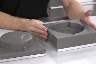
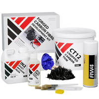
PRODUCTEN DIE IN DIT PROJECT ZIJN GEBRUIKT
Hoewel het niet per se een uitputtende lijst is, werden de volgende gereedschappen en materialen, geleverd door Easy Composites, in dit project gebruikt.
De hieronder getoonde hoeveelheid is de geschatte hoeveelheid die in het project is gebruikt, afgerond naar de dichtstbijzijnde beschikbare kitgrootte of hoeveelheid.
MATERIALEN & VERBRUIKSARTIKELEN
VIDEO-HANDLEIDING
Hoe je Gesmede Koolstofvezelcomponenten Comprimeert
In deze composieten video tutorial laten we zien hoe je solide, hoogwaardige, gesmede koolstofvezel onderdelen maakt met behulp van een tweedelige compressiemal.
In de tutorial gebruiken we een tweedelige compressiemal gemaakt met behulp van een speciale epoxy giethars en een driedelige mal met behulp van een conventionele FDM-printer. Gedurende de tutorial gebruiken we de materialen die zijn opgenomen in de Forged Carbon Fibre Development Kit van Easy Composites.
WAT U GAAT LEREN
In deze video tutorial maken we hoogwaardige, solide gesmede koolstofvezel componenten met behulp van een compressiemethode bij omgevingstemperatuur. We werken met 2 soorten mallen; een hars gegoten mal en een 3D geprinte mal.
Deze tutorial kan worden gevolgd om gesmede koolstofvezel onderdelen te maken die de prestaties van metalen in veel toepassingen evenaren en zelfs overtreffen, en behandelt de volgende onderwerpen:
- Ontwerp van compressiemallen
- Geschikte materialen voor de constructie van mallen
- Voorbereiding van de mal en aanbrengen van lossingsmiddel
- Berekenen van de hoeveelheden vezel en hars
- Lamineren/laadmethoden
- Methoden voor het comprimeren van de mal
- Lossen en afwerken
INTRODUCTIE
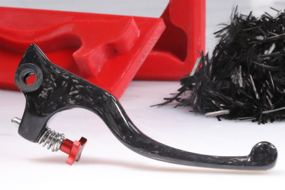
Gesmeed koolstofvezel is de term die is aangenomen om korte of ‘gehakte’ strengen koolstofvezel te beschrijven die in een meerdelige mal worden geperst om sterke, solide geometrieën te creëren die niet praktisch zouden zijn met conventionele composietprocessen.
Er zijn 2 fundamentele benaderingen voor het maken van een gesmeed koolstof onderdeel. De ene is het gebruik van een pre-impregneerd (prepreg) gehakte touw materiaal en dit onder hitte en druk te vormen, de andere is het gebruik van een droge vezel en vloeibare hars systeem en te vormen onder druk, maar zonder hitte. Deze projectgids zal zich richten op de laatste, maar het algemene principe en de ontwerp principes voor de mal zijn hetzelfde voor beide materialen.
Componenten die met deze methode zijn vervaardigd, hebben volledig gevormde oppervlakken, kunnen variërende wanddiktes hebben en bieden uitstekende mechanische prestaties die in plaats van metalen kunnen worden gebruikt om het gewicht in veel toepassingen te verminderen.
Basisprincipes van Het Ontwerpen van Compressiemallen
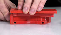
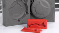
Compressiemal gereedschappen bestaan uit 2 of meer delen die samenkomen en een holte achterlaten waar het onderdeel wordt gevormd. In bijna alle gevallen zal de mal een ‘blok’-achtige vorm hebben om sterkte te bieden en het klem- of compressieproces praktisch te maken.
De belangrijkste overweging bij het ontwerpen van gereedschap voor dit proces is het opnemen van een telescopisch gedeelte waarbij het mannelijke gereedschap als een zuiger in een cilinder fungeert tijdens het sluiten. Dit biedt ruimte om de niet-samengeperste vezel te laden en tijdens het sluiten wordt overtollige hars door de scheidingslijn geperst, maar omdat deze zeer nauwsluitend is, kan de vezel niet ontsnappen, waardoor u de juiste vezel-harsverhouding overhoudt. Dit telescopische of ‘zuigerachtige’ element moet diep genoeg zijn om de mal te laten sluiten voordat de vezel wordt verstoord. De exacte grootte van deze functie is afhankelijk van de vorm en het ontwerp van de mal, maar een algemene regel dat de functie minstens 25% van de diepte van het uiteindelijke onderdeel beslaat, zou een goede schatting zijn. In het geval van een tweedelige mal vereist deze functie een lichte lossingshoek van 2-3 graden om de mal gemakkelijk te kunnen scheiden. Bij meerdelig gereedschap is het vaak mogelijk om de mal zo te ontwerpen dat deze kan worden gescheiden van een volledig parallelle ‘zuiger’-functie.
Materialen voor de constructie van mallen
Voor de productie van compressiemallen in grote volumes worden deze over het algemeen vervaardigd uit bewerkt aluminium of staal. Deze bieden uiteraard een uitstekende sterkte en duurzaamheid, maar zijn duur om te produceren, waardoor ze minder geschikt zijn voor kleine oplages en prototyping.
Een alternatief voor gereedschappen van massief metaal is gereedschap dat is gegoten met epoxyhars. In dit project gebruiken we mallen die zijn gegoten in TC80 tool-cast hars. Dit voorbeeld is gemaakt door de gietstukken van een bestaand spuitgegoten onderdeel te nemen, maar dit zou ook kunnen worden gegoten van een conventioneel patroon of een 3D-print. De resulterende gegoten hars gereedschappen bieden een zeer goede sterkte en duurzaamheid en zouden in staat moeten zijn om tientallen, zo niet honderden componenten te produceren zonder overmatige slijtage. Zie ons cast resin compression tools project voor meer informatie over deze gereedschapsmethode.
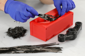
Een andere gereedschapsmethode die we in dit project zullen gebruiken, is direct 3D-geprint PETG-plastic gereedschap. Hoewel dit niet de sterkte en duurzaamheid biedt van massief gereedschap, heeft het het voordeel dat het zeer goedkoop en snel te produceren is en zeer nuttig kan zijn voor kleine oplages en eenmalige prototyping. Het gebruik van dit proces met een 3D-geprinte mal stelt u in staat om componenten te produceren met echt hoge mechanische prestaties zonder verdere specialistische apparatuur of gereedschap. Hiervoor heeft u een correct geconfigureerde en ingestelde FDM-printer nodig. In dit project hebben we de uitstekende Ultimaker S5 gebruikt, die met zijn presets en intuïtieve gebruikersinterface 3D-printen eenvoudig maakt, maar elke printer die correct is geconfigureerd, kan uiteraard worden gebruikt. Als u advies zoekt over 3D-printen, bevelen we graag onze leveranciers van Dynamism aan. Hoewel andere filamentmaterialen kunnen worden gebruikt, hebben we vastgesteld dat PETG geweldige lossingseigenschappen biedt en nauwkeurig en gemakkelijk te printen is, waardoor het een uitstekende keuze is. Bij het printen van compressiemallen moet de vulling ongeveer 75% of hoger zijn om voldoende sterkte en stijfheid te bieden tijdens de compressie. Het gebruik van een laaghoogte van 0,15 mm of minder zorgt ook voor een beter oppervlak voor de lossing.
Klanten die willen experimenteren met de daadwerkelijke mallen die in de video worden getoond, kunnen de gesmede koolstofvezel compressievorm CAD-bestanden downloaden, waaronder de remhendel, de schakelpaddle en de drijfstangmallen in zowel IGES- als STL-bestanden; let op: de STL-bestanden zijn één bestand per maldeel.
WAT U NODIG HEEFT
Materialen en Apparatuur die Nodig Zijn voor Het Onderdeel
Lossingsmiddel
RW4 hoogwaardige spuitlossingswas is het aanbevolen lossingssysteem voor compressiemoulding bij omgevingstemperatuur. Dit lossingsmiddel presteert bijzonder goed bij het lossen van stijve gietstukken en mallen van elkaar, omdat het een dikke barrière vormt die relatief zacht is en daardoor indien nodig een beetje kan bewegen tijdens het lossen.
Vulwas
Vulwas en/of plasticine is vaak nuttig voor het afdichten van schroefdraden op malbouten of om uitwerpgaten in de mal op te vullen en af te dichten.
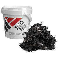
Chopped Touw
CT12 chopped touw is perfect geschikt voor dit proces, het heeft strengen die zijn gehakt op 12mm lengte, wat een geweldige balans biedt tussen vormbaarheid en sterkte.
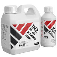
Epoxyhars
De IN2-hars heeft bewezen uitstekende bevochtiging en vloei te bieden in dit proces, wat cruciaal is voor succesvol vormen.
PROJECTSPECIFICATIE
1. Bereid de mal voor
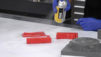
De mallen moeten worden geïnspecteerd en gecontroleerd op mogelijke ondersnijdingen of imperfecties die een probleem kunnen veroorzaken bij het lossen. In het geval van een 3D-geprinte mal kan het zijn dat het vierkant scheren van hoeken met een mes de nauwkeurigheid van de sluiting verbetert. Zodra de mallen zijn gecontroleerd, kan het lossingsmiddel worden aangebracht.
De RW4 spuitwas wordt aangebracht door een dunne film over de mal te spuiten en deze ongeveer 5-10 minuten te laten drogen en vervolgens opnieuw aan te brengen. Doorgaans bieden 3 of 4 dunne lagen voldoende lossing. Vermijd het spuiten van de was in één dikke laag, omdat dit veel langer duurt om te drogen dan meerdere dunnere lagen. Het lossingsmiddel moet worden aangebracht op alle vlakken en scheidingsvlakken van de mal, omdat de hars hier tijdens de compressiefase in zal dringen.
Eventuele uitwerp gaten in de mal moeten nu worden afgedicht met vulwas, deze moeten stevig worden gevuld tegen een harde stop, anders zal de druk van het vormproces ze waarschijnlijk naar buiten forceren. Alle bouten in de mal moeten de schroefdraad gevuld hebben met de vulwas om te voorkomen dat ze in het gereedschap worden gebonden.
2. Bereken de benodigde hoeveelheid vezel
Het nauwkeurig berekenen van de juiste vezelbelasting voor de mal is waarschijnlijk de belangrijkste factor voor succes met dit proces. De eerste stap bij het berekenen van de benodigde hoeveelheid vezel is het bepalen van het volume van uw afgewerkte component. Als u met CAD werkt, is dit heel eenvoudig en kan dit worden opgezocht in het eigenschappenvenster van een solid body. In het geval van mallen die van een bestaand component zijn genomen, wordt het volume doorgaans berekend door het originele component te wegen, de dichtheid van het materiaal waaruit het is gemaakt te bepalen en vervolgens het volume daaruit te berekenen. Bijvoorbeeld, als we een spuitgegoten onderdeel hebben dat 100 g weegt en is gemaakt van nylon 6 met 30% glasvezel (PA6 GF30), dan is de dichtheid hiervan vastgesteld op 1,3 gram per kubieke centimeter, dus gewicht onderdeel / dichtheid = volume of 100 / 1,3 = 76,92.
Zodra het volume van het onderdeel bekend is, kan het gewicht van het afgewerkte gesmede koolstof onderdeel worden berekend. Voor een snelle berekening vanuit een bekend volume kunt u een vereenvoudigde methode gebruiken van 0,84 g/cc voor uw vezelberekening, maar om de reden beter uit te leggen, wordt de volgende basismethode gebruikt: De dichtheid van gesmede koolstofvezel is doorgaans 1,4 g/cc, dus in ons vorige voorbeeld dichtheid * volume = gewicht onderdeel, dus 1,4 * 76,92 = 107,69
Nu we het uiteindelijke gewicht van het onderdeel hebben, kunnen we de hoeveelheid vezel berekenen die nodig is om de optimale vezel-harsverhouding te bereiken, die voor dit proces over het algemeen 60/40 is (vezel/hars), op basis van gewicht. We kunnen dus de hoeveelheid vezel berekenen die we nodig hebben door simpelweg het gewicht van het afgewerkte onderdeel te vermenigvuldigen met 0,6, dus in ons voorbeeld: 107,69 * 0,6 = 64,61 g CT12-vezel.
De benodigde vezel moet nauwkeurig worden afgewogen in een aparte container die vervolgens kan worden gebruikt totdat deze leeg is tijdens het lamineren van het onderdeel.
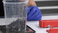
3. Bereken de benodigde hoeveelheid hars
De hoeveelheid benodigde IN2-hars kan snel worden geschat door een batch te mengen die 25% zwaarder is dan de berekende hoeveelheid vezel, dus doorgaand met ons voorbeeld hebben we vezelgewicht 64,61 * 1,25 = 80,76 g IN2-hars (gemengd). Deze eenvoudige methode geeft u de overtollige hars die nodig is voor dit proces, een groot deel van deze hars wordt tijdens het proces eruit geperst, het uiteindelijke onderdeel zelf heeft 43,08 g hars [107,69 (eindgewicht) – 64,61 (vezelgewicht) = 43,08 g]. Afhankelijk van de grootte en complexiteit van het onderdeel dat u produceert, heeft u mogelijk extra hars nodig om het onderdeel effectief te lamineren, dit kan naar behoefte worden gemengd tijdens het lamineren.
De hars mag pas vlak voor gebruik worden gemengd, net als bij alle epoxy's is nauwkeurig wegen en mengen volgens de instructies essentieel.
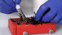
4. Lamineer het onderdeel
Lamineren in dit gesmede proces is eigenlijk heel vergelijkbaar met een typisch nat-in-nat-proces; de mal moet eerst een dunne laag hars hebben die met een kwast wordt aangebracht, dit helpt om de eerste laag vezel te laten hechten en zorgt ervoor dat het hele oppervlak goed nat is, de vezel moet vervolgens licht over het oppervlak worden gestrooid en worden geconsolideerd en nat gemaakt door te stippelen met een kwast totdat de vezel verzadigd is en vervolgens herhaald totdat de malholte is gevuld, er moet zorg worden besteed aan het gelijkmatig laden van de vezel en het ongeveer weergeven van de uiteindelijke vorm van het onderdeel. Stompe gereedschappen of 'dibbers' zullen vaak nuttig blijken om de vezel in strakke en gedetailleerde gebieden te drukken. U zult merken dat er tijdens dit proces meer vezels lijken te zijn dan in de mal passen en dat de holte overvol zal zijn, dit is normaal en zal tijdens de compressie in de holte worden gedwongen.
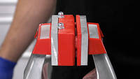
5. Sluit en comprimeer de mallen
Zodra alle vezels in de mallen zijn geladen, kunnen ze worden gesloten en samengeperst. Voor kleinere malgereedschappen bieden een bankschroef of G-klemmen voldoende klemkracht, voor grotere gereedschappen kan een pneumatische of hydraulische pers geschikt zijn. Hoe de compressie ook wordt bereikt, het is belangrijk om het gereedschap langzaam te sluiten, vooral bij meer fragiele mallen zoals die welke zijn geprint, de reden om langzaam te sluiten is om de hars de tijd te geven om in de holte te stromen en overtollige hars eruit te laten stromen. Als de mal te snel wordt gesloten, kan dit een hydraulische vergrendeling veroorzaken die een enorme kracht op de mallen zou uitoefenen, waardoor ze mogelijk beschadigd raken. In de meeste gevallen kan het gereedschap geleidelijk over ongeveer 5 minuten worden vastgeklemd. Zodra het gereedschap volledig samenkomt of 'bottom-out', moet het onderdeel onder druk worden gelaten totdat het harssysteem is uitgehard.
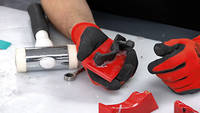
6. Bijsnijden en afwerken
Na het ontvormen houdt u wat flash over bij de scheidingslijnen. Dit kan snel worden verwijderd met een scherp mes of schuurpapier. Eventuele resten van lossingsmiddel kunnen effectief worden verwijderd met malreiniger of een soortgelijk oplosmiddel. Hoewel deze onderdelen bijna al hun potentiële structurele prestaties direct uit de mal zullen hebben, kan een verwarmde nabehandeling worden uitgevoerd om de eigenschappen van de hars te maximaliseren. Raadpleeg het technische gegevensblad van de IN2 voor meer informatie.
Het component zou direct uit de mal volledig bruikbaar zijn, maar als het component bedoeld is voor een cosmetische toepassing, kan een glanzende, blank gelakte afwerking de voorkeur hebben. Dit kan worden gespoten met een 2K blanke lak of worden aangebracht met een XCR coatinghars. Om voor te bereiden op een van deze afwerkingen, moeten de onderdelen worden opgeruwd en gevlakt met korrel 400 nat en droog voorafgaand aan het aanbrengen.
Een andere afwerkingsoptie die geen extra coating vereist, is het vlakken en schuren van het ruwe, ontvormde onderdeel tot een fijne korrel 1200 en vervolgens het aanbrengen van een autowas om een ruwe satijnen afwerking achter te laten.
DISCUSSIE (23)
Deel al uw vragen of opmerkingen over deze videohandleiding.
Het volume van de Paddle Shifter is 28,6 cm³.
Het is niet iets dat we eerder hebben gezien. In wezen zou je het meer moeten ontwerpen als een spuitgietmatrijs met een pad voor hars naar binnen en ontluchtings-/vacuümpaden voor lucht en overtollige hars om naar buiten te gaan. 3D-prints kunnen ook problemen hebben onder vacuüm, waardoor uw opties voor malmaterialen worden beperkt.
Ja, potentieel wel, maar 1,5 mm is erg dicht bij de ondergrens van de wanddikte die je realistisch gezien met dit proces zou kunnen vormen. Of je deze ribben of flenzen succesvol zou kunnen vormen, hangt af van de specifieke geometrie (hoe diep zijn ze bijvoorbeeld), hoe je de mal splitst en de vorm van het totale vormstuk. Je kunt je waarschijnlijk de factoren voorstellen die het proces helpen of hinderen, met name de primaire 'richting' van de compressie wanneer de malhelften samenkomen. Er zouden posities kunnen zijn waarin deze ribben of flenzen zich bevinden waardoor ze vormbaar zouden zijn, maar er zijn andere posities waarin ze zich zouden kunnen bevinden waardoor ze bijna onmogelijk te vullen en vervolgens succesvol samen te persen zouden zijn. Als je wat praktische ervaring opdoet met het proces op een eenvoudiger onderdeel, krijg je waarschijnlijk een goed inzicht in wat realistisch is en wat niet voordat je het complexere onderdeel probeert.
Het is misschien mogelijk om dat te doen. U moet zorgen voor een zorgvuldige plaatsing voor het beste effect. Mogelijk wilt u ook enkele tests uitvoeren tot falen om te zien of de faalmethode iets ongewenst doet wanneer de twee materialen zich anders beginnen te gedragen bij hoge belastingen.
Geweldig om te horen dat je de sprong hebt gewaagd! Laat ons weten hoe het gaat, het zou geweldig zijn om meer onderdelen te zien die klanten met de kit hebben gemaakt. We hebben al een paar goede voorbeelden gezien, maar het is fascinerend om de verschillende componenten te zien die mensen maken.
Ja, dat zou kunnen. Ten eerste, afhankelijk van het plastic dat je hebt gebruikt voor de 3D-print en het type high-build primer dat je gebruikt, kan het zijn dat de verf reageert met, of op zijn minst enigszins verzacht, de 3D-print, dus ik zou aanraden dit eerst te testen. Ten tweede kun je ook problemen ondervinden om de epoxycomponent goed uit de mal te krijgen als je deze met primer hebt behandeld. Dit is zeker niet gegarandeerd, maar het oplosmiddel in spuitbussen, inclusief primers, heeft vaak een negatieve invloed op het lossingsmiddel (in dit geval de spuitwas), wat kan veroorzaken dat de component in de mal blijft plakken, of, net zo waarschijnlijk, dat de primer van de mal loskomt, maar aan je onderdeel blijft kleven. Nogmaals, als je deze route wilt volgen, plan dan om het eerst te testen.
Als u het oppervlak van uw mal op een meer betrouwbare manier wilt verbeteren, overweeg dan om een speciale epoxycoatinghars te gebruiken, zoals onze XCR Epoxy Coating Resin, die op 3D-prints kan worden aangebracht en een betrouwbare, volledig compatibele schaal creëert waar u geen problemen mee zult hebben om deze los te laten. U zult ons deze hars zien aanbrengen op een 3D-print in onze drone shell tutorial.
Hangt volledig af van het gebruikte harssysteem. Sommige kunststoffen, zoals PETG, zijn van nature in staat om los te laten van harsen. Als de gebruikte kunststofhars een type kunststof is dat van nature loslaat, dan zou de gladdere afwerking van met hars geprinte onderdelen waarschijnlijk een iets gemakkelijkere lossing betekenen.
Er wordt een insert in de hendel gelijmd om de schroefdraad te ondersteunen. Gesmeed koolstofvezel is niet sterk genoeg om een schroefdraad te dragen die erin is gesneden.
De hars heeft een hogere viscositeit, dus het is mogelijk minder effectief, vooral bij grotere onderdelen. U kunt de hars en de mal voorzichtig verwarmen, maar u moet oppassen voor de exotherme reactie die kan optreden. De compressiefase zal zeker moeten worden vertraagd, zodat de dikkere hars kan worden samengedrukt en overtollige hars eruit kan worden geperst.
Nee, de hars is vrij laag viskeus, wat helpt om luchtinsluiting te voorkomen en ook de compressie zelf helpt om eventuele resterende lucht en overtollige hars eruit te persen.
Hoi Justin, geen domme vragen hier! Ja, je zou dit kunnen doen met glasvezel, maar - natuurlijk - je zou gehakte glas roving nodig hebben (in plaats van gehakte koolstof touw). Daarna zou het proces identiek zijn (hoewel de dichtheid van glas groter is dan koolstof, dus uw volumeberekening zou moeten worden aangepast aan het verschil). Qua prestaties zou een met glas versterkt onderdeel, zoals je al had geraden, sterker zijn dan een niet-versterkte plastic, maar niet zo sterk (of stijf, afhankelijk van je prioriteiten) als aluminium of koolstof.
Nee, unidirectionele koolstofvezel is bijna het tegenovergestelde. Unidirectionele versterking is continue vezelversterking waarbij alle vezels in dezelfde richting lopen, het wordt gebruikt wanneer u de oriëntatie weet waarin u de meeste sterkte wilt toevoegen. Het gehakte touw dat we hier gebruiken, zijn relatief korte strengen koolstofvezel in willekeurige oriëntatie, die in alle richtingen sterkte bieden. Het gehakte touw is echter cruciaal voor deze toepassing, omdat de korte strengen de versterking in staat stellen om te 'stromen' en zich te herverdelen in de mal wanneer deze wordt samengeperst.
In principe zou het mogelijk kunnen zijn en we hebben het niet geprobeerd, dus we kunnen het niet met zekerheid zeggen, maar onze zorg zou zijn dat het compressie vormproces sterk afhankelijk is van het vermogen van de versterking om relatief vrij te bewegen en zich te herverdelen in de mal. Geweven doek, gemaakt van continue vezels, zou niet in staat zijn om op deze manier te bewegen en dus zou ten minste een deel van de versterking die u toevoegt, deze herverdeling niet kunnen uitvoeren. Echter, voor een enkele laag, als er een redelijke hoeveelheid gehakte touw achter zit, zou het prima kunnen werken. Het zou zeker beperkt moeten blijven tot vlakke gebieden. Als je het probeert, laat ons dan weten hoe het gaat.
Nou, met 80 onderdelen per dag met behulp van een vacuümzakproces, neem ik aan dat je meer dan één gereedschap hebt? Zo ja, dan zou het vermenigvuldigen van het gereedschap ook de productiecapaciteit verhogen met behulp van een compressiemethode. Bovendien zouden er veel manieren zijn om de productie te versnellen met behulp van dit compressiemethode; je zou stijve (gegoten of uit knuppels machinaal bewerkte) gereedschappen nodig hebben, maar je zou de gereedschappen kunnen verwarmen zodra de compressie is voltooid en de hars in ongeveer een uur kunnen uitharden. Je zult nooit de 10 onderdelen per uur halen die je noemde, maar afgezien van een paar zeer geavanceerde warmpersprocessen - ken ik echt niet veel in composieten dat zo snel kan cyclen.
Ervan uitgaande dat we het hebben over een Honda *auto* motor kleppendeksel, dan zou ik zeggen dat je waarschijnlijk het schaalniveau en de vorm voorbij bent waarvoor dit proces het meest geschikt is. Dat wil niet zeggen dat het niet mogelijk zou zijn om zoiets groots te maken, maar het zou waarschijnlijk gemakkelijker en beter zijn om het te maken met behulp van een conventionele enkelzijdige mal en prepreg, harsinjectie of vacuümzakken te gebruiken voor de layup.
Een autoclaaf doet twee dingen: hij levert druk en warmte. Als je 'prepreg' koolstofvezel gebruikt om je onderdelen te maken, betekent dit dat de hars al is gecombineerd met de koolstofvezel en al is gemengd met zijn verharder (daarom worden ze in een vriezer bewaard), maar om de hars uit te harden heb je *warmte* nodig, dit betekent dat prepregs moeten worden uitgehard in een oven of autoclaaf. De extra druk van een autoclaaf helpt om de versteviging te consolideren, waardoor de vezelverhouding toeneemt en het percentage holle ruimtes afneemt. Dit is ook wat er gebeurt bij compressiemoulding, waarbij - als het goed wordt gedaan - de druk gelijk kan zijn aan of hoger dan de druk in een autoclaaf.
Als je een hars systeem gebruikt dat is ontworpen voor uitharding bij omgevingstemperatuur en je past een druk toe die gelijk is aan een autoclaaf, dan zouden de mechanische eigenschappen van het resulterende onderdeel zeer vergelijkbaar zijn. Uiteindelijk is het gebruik van een autoclaaf vaak meer een praktische overweging (d.w.z. wat is de beste manier om dit specifieke onderdeel/deze vorm te maken?) dan dat het een superieur fabricageproces is in termen van de prestaties van het onderdeel.
EEN OPMERKING OF VRAAG ACHTERLATEN
Downloads (1)
| CAD-Bestanden van Gesmede Koolstof Voorbeeld Compressiemallen |
PRODUCTEN DIE IN DIT PROJECT ZIJN GEBRUIKT
Hoewel het niet per se een uitputtende lijst is, werden de volgende gereedschappen en materialen, geleverd door Easy Composites, in dit project gebruikt.
De hieronder getoonde hoeveelheid is de geschatte hoeveelheid die in het project is gebruikt, afgerond naar de dichtstbijzijnde beschikbare kitgrootte of hoeveelheid.
MATERIALEN & VERBRUIKSARTIKELEN
DISCUSSIE (23)
Deel al uw vragen of opmerkingen over deze videohandleiding.
Het volume van de Paddle Shifter is 28,6 cm³.
Het is niet iets dat we eerder hebben gezien. In wezen zou je het meer moeten ontwerpen als een spuitgietmatrijs met een pad voor hars naar binnen en ontluchtings-/vacuümpaden voor lucht en overtollige hars om naar buiten te gaan. 3D-prints kunnen ook problemen hebben onder vacuüm, waardoor uw opties voor malmaterialen worden beperkt.
Ja, potentieel wel, maar 1,5 mm is erg dicht bij de ondergrens van de wanddikte die je realistisch gezien met dit proces zou kunnen vormen. Of je deze ribben of flenzen succesvol zou kunnen vormen, hangt af van de specifieke geometrie (hoe diep zijn ze bijvoorbeeld), hoe je de mal splitst en de vorm van het totale vormstuk. Je kunt je waarschijnlijk de factoren voorstellen die het proces helpen of hinderen, met name de primaire 'richting' van de compressie wanneer de malhelften samenkomen. Er zouden posities kunnen zijn waarin deze ribben of flenzen zich bevinden waardoor ze vormbaar zouden zijn, maar er zijn andere posities waarin ze zich zouden kunnen bevinden waardoor ze bijna onmogelijk te vullen en vervolgens succesvol samen te persen zouden zijn. Als je wat praktische ervaring opdoet met het proces op een eenvoudiger onderdeel, krijg je waarschijnlijk een goed inzicht in wat realistisch is en wat niet voordat je het complexere onderdeel probeert.
Het is misschien mogelijk om dat te doen. U moet zorgen voor een zorgvuldige plaatsing voor het beste effect. Mogelijk wilt u ook enkele tests uitvoeren tot falen om te zien of de faalmethode iets ongewenst doet wanneer de twee materialen zich anders beginnen te gedragen bij hoge belastingen.
Geweldig om te horen dat je de sprong hebt gewaagd! Laat ons weten hoe het gaat, het zou geweldig zijn om meer onderdelen te zien die klanten met de kit hebben gemaakt. We hebben al een paar goede voorbeelden gezien, maar het is fascinerend om de verschillende componenten te zien die mensen maken.
Ja, dat zou kunnen. Ten eerste, afhankelijk van het plastic dat je hebt gebruikt voor de 3D-print en het type high-build primer dat je gebruikt, kan het zijn dat de verf reageert met, of op zijn minst enigszins verzacht, de 3D-print, dus ik zou aanraden dit eerst te testen. Ten tweede kun je ook problemen ondervinden om de epoxycomponent goed uit de mal te krijgen als je deze met primer hebt behandeld. Dit is zeker niet gegarandeerd, maar het oplosmiddel in spuitbussen, inclusief primers, heeft vaak een negatieve invloed op het lossingsmiddel (in dit geval de spuitwas), wat kan veroorzaken dat de component in de mal blijft plakken, of, net zo waarschijnlijk, dat de primer van de mal loskomt, maar aan je onderdeel blijft kleven. Nogmaals, als je deze route wilt volgen, plan dan om het eerst te testen.
Als u het oppervlak van uw mal op een meer betrouwbare manier wilt verbeteren, overweeg dan om een speciale epoxycoatinghars te gebruiken, zoals onze XCR Epoxy Coating Resin, die op 3D-prints kan worden aangebracht en een betrouwbare, volledig compatibele schaal creëert waar u geen problemen mee zult hebben om deze los te laten. U zult ons deze hars zien aanbrengen op een 3D-print in onze drone shell tutorial.
Hangt volledig af van het gebruikte harssysteem. Sommige kunststoffen, zoals PETG, zijn van nature in staat om los te laten van harsen. Als de gebruikte kunststofhars een type kunststof is dat van nature loslaat, dan zou de gladdere afwerking van met hars geprinte onderdelen waarschijnlijk een iets gemakkelijkere lossing betekenen.
Er wordt een insert in de hendel gelijmd om de schroefdraad te ondersteunen. Gesmeed koolstofvezel is niet sterk genoeg om een schroefdraad te dragen die erin is gesneden.
De hars heeft een hogere viscositeit, dus het is mogelijk minder effectief, vooral bij grotere onderdelen. U kunt de hars en de mal voorzichtig verwarmen, maar u moet oppassen voor de exotherme reactie die kan optreden. De compressiefase zal zeker moeten worden vertraagd, zodat de dikkere hars kan worden samengedrukt en overtollige hars eruit kan worden geperst.
Nee, de hars is vrij laag viskeus, wat helpt om luchtinsluiting te voorkomen en ook de compressie zelf helpt om eventuele resterende lucht en overtollige hars eruit te persen.
Hoi Justin, geen domme vragen hier! Ja, je zou dit kunnen doen met glasvezel, maar - natuurlijk - je zou gehakte glas roving nodig hebben (in plaats van gehakte koolstof touw). Daarna zou het proces identiek zijn (hoewel de dichtheid van glas groter is dan koolstof, dus uw volumeberekening zou moeten worden aangepast aan het verschil). Qua prestaties zou een met glas versterkt onderdeel, zoals je al had geraden, sterker zijn dan een niet-versterkte plastic, maar niet zo sterk (of stijf, afhankelijk van je prioriteiten) als aluminium of koolstof.
Nee, unidirectionele koolstofvezel is bijna het tegenovergestelde. Unidirectionele versterking is continue vezelversterking waarbij alle vezels in dezelfde richting lopen, het wordt gebruikt wanneer u de oriëntatie weet waarin u de meeste sterkte wilt toevoegen. Het gehakte touw dat we hier gebruiken, zijn relatief korte strengen koolstofvezel in willekeurige oriëntatie, die in alle richtingen sterkte bieden. Het gehakte touw is echter cruciaal voor deze toepassing, omdat de korte strengen de versterking in staat stellen om te 'stromen' en zich te herverdelen in de mal wanneer deze wordt samengeperst.
In principe zou het mogelijk kunnen zijn en we hebben het niet geprobeerd, dus we kunnen het niet met zekerheid zeggen, maar onze zorg zou zijn dat het compressie vormproces sterk afhankelijk is van het vermogen van de versterking om relatief vrij te bewegen en zich te herverdelen in de mal. Geweven doek, gemaakt van continue vezels, zou niet in staat zijn om op deze manier te bewegen en dus zou ten minste een deel van de versterking die u toevoegt, deze herverdeling niet kunnen uitvoeren. Echter, voor een enkele laag, als er een redelijke hoeveelheid gehakte touw achter zit, zou het prima kunnen werken. Het zou zeker beperkt moeten blijven tot vlakke gebieden. Als je het probeert, laat ons dan weten hoe het gaat.
Nou, met 80 onderdelen per dag met behulp van een vacuümzakproces, neem ik aan dat je meer dan één gereedschap hebt? Zo ja, dan zou het vermenigvuldigen van het gereedschap ook de productiecapaciteit verhogen met behulp van een compressiemethode. Bovendien zouden er veel manieren zijn om de productie te versnellen met behulp van dit compressiemethode; je zou stijve (gegoten of uit knuppels machinaal bewerkte) gereedschappen nodig hebben, maar je zou de gereedschappen kunnen verwarmen zodra de compressie is voltooid en de hars in ongeveer een uur kunnen uitharden. Je zult nooit de 10 onderdelen per uur halen die je noemde, maar afgezien van een paar zeer geavanceerde warmpersprocessen - ken ik echt niet veel in composieten dat zo snel kan cyclen.
Ervan uitgaande dat we het hebben over een Honda *auto* motor kleppendeksel, dan zou ik zeggen dat je waarschijnlijk het schaalniveau en de vorm voorbij bent waarvoor dit proces het meest geschikt is. Dat wil niet zeggen dat het niet mogelijk zou zijn om zoiets groots te maken, maar het zou waarschijnlijk gemakkelijker en beter zijn om het te maken met behulp van een conventionele enkelzijdige mal en prepreg, harsinjectie of vacuümzakken te gebruiken voor de layup.
Een autoclaaf doet twee dingen: hij levert druk en warmte. Als je 'prepreg' koolstofvezel gebruikt om je onderdelen te maken, betekent dit dat de hars al is gecombineerd met de koolstofvezel en al is gemengd met zijn verharder (daarom worden ze in een vriezer bewaard), maar om de hars uit te harden heb je *warmte* nodig, dit betekent dat prepregs moeten worden uitgehard in een oven of autoclaaf. De extra druk van een autoclaaf helpt om de versteviging te consolideren, waardoor de vezelverhouding toeneemt en het percentage holle ruimtes afneemt. Dit is ook wat er gebeurt bij compressiemoulding, waarbij - als het goed wordt gedaan - de druk gelijk kan zijn aan of hoger dan de druk in een autoclaaf.
Als je een hars systeem gebruikt dat is ontworpen voor uitharding bij omgevingstemperatuur en je past een druk toe die gelijk is aan een autoclaaf, dan zouden de mechanische eigenschappen van het resulterende onderdeel zeer vergelijkbaar zijn. Uiteindelijk is het gebruik van een autoclaaf vaak meer een praktische overweging (d.w.z. wat is de beste manier om dit specifieke onderdeel/deze vorm te maken?) dan dat het een superieur fabricageproces is in termen van de prestaties van het onderdeel.
EEN OPMERKING OF VRAAG ACHTERLATEN
100% VEILIG
BETAALMETHODEN
Easy Composites EU B.V., geregistreerd in Nederland 73601195. Alle inhoud auteursrecht (C) Easy Composites Ltd, 2025. Alle rechten voorbehouden.