Need any help or advice?![]() +44 (0)1782 454499
+44 (0)1782 454499
VIDEOS IN THIS SERIES
This video is part 3 of a 4 part series: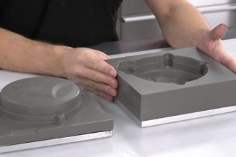
PRODUCTS USED IN THIS PROJECT
Although not necessarily an exhaustive list, the following tools and materials, supplied by Easy Composites, were used in this project.
The quantity shown below is the approximate amount used in the project rounded up to the nearest available kit size or quantity.
COMPONENT MATERIALS

VIDEO TUTORIAL
Investigating the Mechanical Performance of 'Forged' Carbon Fibre Components
How do 'forged' carbon fibre components compare to cast aluminium, continuous carbon fibre, Markforged 3D printed carbon, and 3D printed 'onyx'?
In this video we look into the mechanical properties of components that have been compression moulded using relatively short strand chopped tow carbon fibre reinforcement; a process that has come to be known as 'forged carbon fibre'.
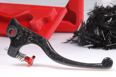
Having demonstrated in a previous tutorial how the forged carbon fibre process can be used to produce a range of fully moulded structural components, such as a brake lever or engine cover component, we were keen to see exactly how well carbon fibre components made in this way compared to their most likely alternative; cast aluminium, as well as a Markforged 3D print, 'onyx' 3D print and a 'forged' component optimised with some continuous fibre placement.
Watch the video to see how these different materials compare to each other in a range of conventional mechanical tests or read on to find out more.
Definition of Forged Carbon Fibre
What is 'forged carbon fibre'?
Throughout this investigation, and our previous video tutorial on the same subject, we have chosen to use the term 'forged carbon fibre', however we acknowledge that although the term is quite widely used, there is little consensus on its exact meaning and also some debate about the appropriateness of the word 'forged' in a composites context at all.
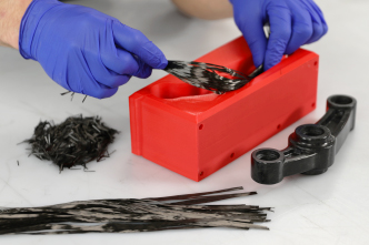
Whilst there may be other definitions, for the purposes of clarity we are defining 'forged carbon fibre' as the name given to the process of compression moulding a carbon fibre component using randomly oriented short strand carbon fibre reinforcement and a resin matrix. As such, the term could be used both to describe compression moulding chopped tow prepreg, or dry chopped carbon fibre tow with a liquid resin - as we have used for this investigation.
Materials on Test
The focus of this investigation was primarily to produce comparative data, comparing the mechanical properties of forged carbon fibre components to some alternative materials which may be considered for the low volume production of small to medium sized, fully moulded components.
Cast Aluminium
Our 'real world' aluminium component was an aftermarket aluminium brake lever for a trials motorcycle made from an unknown grade of aluminium.
The aluminium test tokens were made from 6082 T6 grade aluminium, which is a typical grade of aluminium used for many structural aluminium components.
Markforged Continuous Fibre 3D Printed Carbon Fibre
Markforged 3D printers are highly specialised 3D printers which are capable of printing components using filament reinforced with continuous fibres, including carbon fibre. This technology represents the pinnacle of 3D printed carbon fibre and is claimed to produce components with mechanical properties comparable to aluminium. Markforged 'continuous filament' 3D prints are printed using two heads, one laying a 'base' and the other laying the continuous fibre. For a 'continuous fibre' carbon fibre print, the base filament is Markforged 'Onyx', a nylon filament which is itself enhanced with the addition of very short strand (milled) carbon fibre.
Our component and test tokens were printed by 3d People on a Markforged printer using the maximum amount of continuous carbon fibre and at 100% fill. The carbon fibre was aligned down the length of the lever and wrapped around the pivot point to yield the best possible performance from this technology.
We do not own a Markforged printer, we did not discuss this project with Markforged and we paid retail price for our sample 3D prints.
3D Printed Onyx
'Onyx' filament from Markforged is a nylon FDM print filament which has been enhanced with very short strand milled carbon fibre. Although Onyx is designed for Markforged 3D printers, similar carbon fibre enhanced thermoplastic filaments are widely available and can be used in many conventional FDM printers. Due to the very short length (typically 30µm) of the carbon fibres used in these 'carbon enhanced' filaments, the improvement to the mechanical properties of the resulting print is very limited.
Our 3D printed Onyx brake lever and test tokens were printed on a Markforged 3D printer without any continuous fibre placement. They were printed on 100% fill. No optimisation of fibre orientation is possible with this print technology. These prints represent the best mechanical performance that is likely to be possible from a conventional FDM 3D printer.
Forged Carbon Fibre
The first set of forged carbon fibre Produced by compression moulding randomly oriented dry chopped-tow carbon fibre with a low viscosity liquid epoxy resin in an FDM 3D printed compression mould. Full information on the process used to produce the forged carbon fibre component can be found in our How to Compression Mould Forged Carbon Fibre video tutorial and article.
'Optimised' Forged Carbon Fibre
The second set of forged carbon fibre samples for test were produced using the exact same process used to product the standard forged carbon fibre components but with cut lengths of continuous carbon fibre used in place of some of the chopped-tow reinforcement. Continuous lengths of carbon fibre tow were laid lengthways down the lever and also wrapped around the pivot point to add additional strength in the high load areas.
Using a combination of randomly oriented chopped tow, together with specifically oriented long strand carbon fibre tow creates a hybrid reinforcement solution which leverages the advantages of both reinforcement formats; the chopped tow providing a 'mobile' reinforcement which can move and flow into all areas of the mould under pressure, with the unidirectional carbon fibre providing maximum strength and stiffness exactly where it is needed.
Material Densities
When comparing the mechanical properties of the various materials, it is important to remember that the densities of the various materials on test vary considerably. 'Specific' mechanical properties can be calculated by dividing their standard mechanical properties by their density.
| Material | Density g/cm³ |
|---|---|
| Aluminium | 2.73 |
| Forged Carbon Fibre | 1.5 |
| Optimised Forged Carbon Fibre | 1.58 |
| Markforged Continuous Carbon Fibre | 1.15 |
| Onyx | 1.04 |
Results
The aim of this investigation was not to provide definitive, robust mechanical data for compression moulded forged carbon fibre but rather to provide fair and accurate comparative data comparing forged carbon fibre to cast aluminium and the best 3D printed carbon fibre technology in a real-world application. As such, no formal ISO or ASTM standards were applied, and some units have been substituted where we believe alternatives would be more meaningful to a general audience.
Lever Pull Test
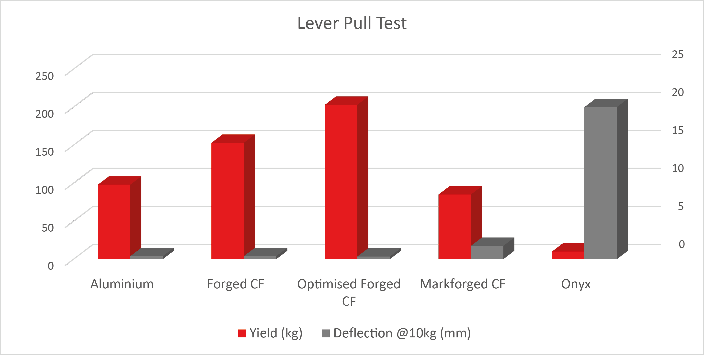
| Material | Component Weight (g) | Yield (kg) | Deflection @10kg (mm) |
|---|---|---|---|
| Aluminium | 46.7 | 98 | 0.4 |
| Forged Carbon Fibre | 24.7 | 153 | 0.4 |
| Optimised Forged Carbon Fibre | 25.2 | 203 | 0.35 |
| Markforged Continuous Carbon Fibre | 19.9 | 85 | 1.75 |
| Onyx | 17.9 | 10 | 20 |
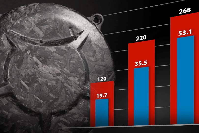
Flexural Test
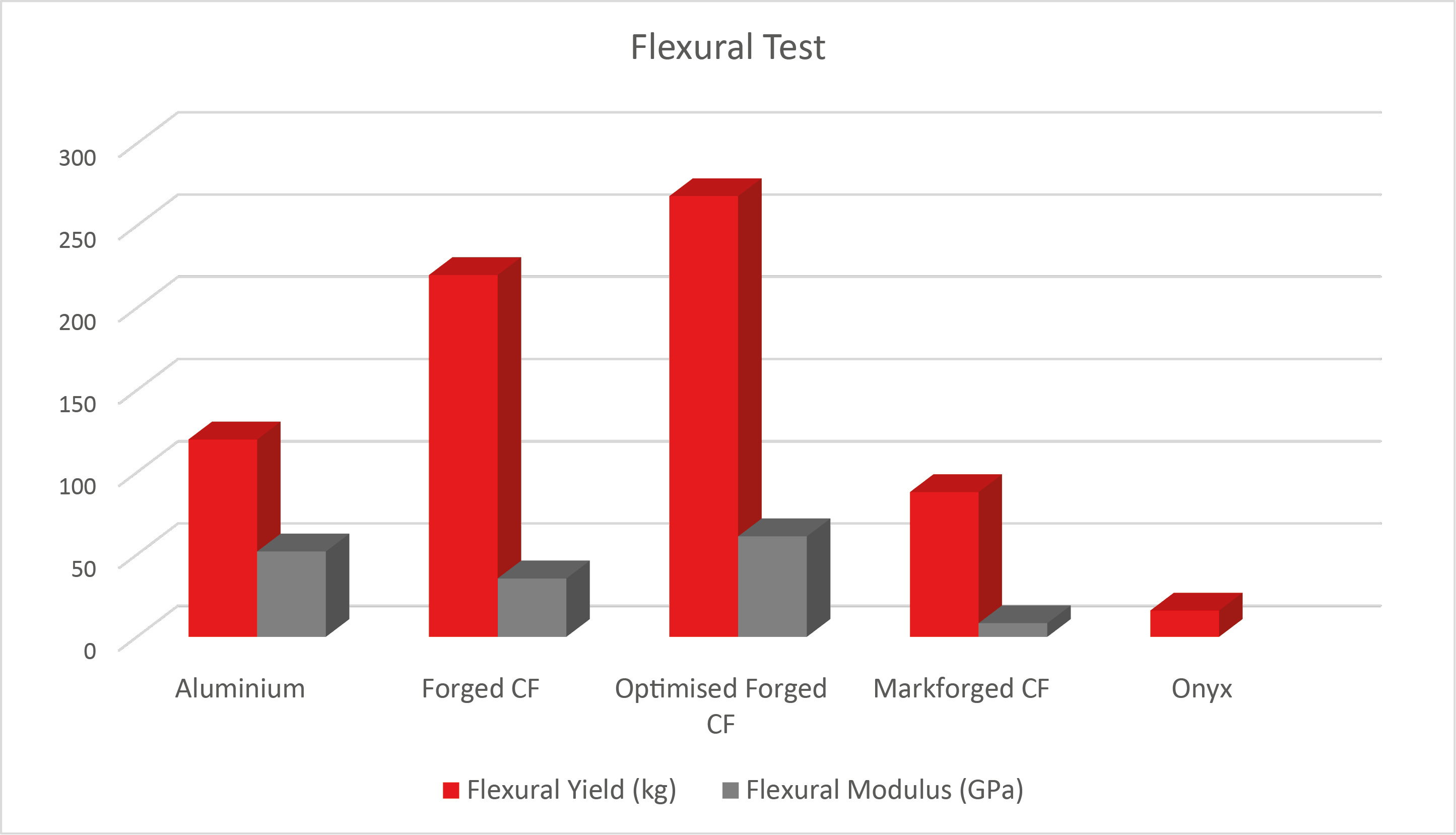
| Material | Flexural Yield (kg) | Flexural Modulus (GPa) |
|---|---|---|
| Aluminium | 120 | 51.9 |
| Forged Carbon Fibre | 220 | 35.5 |
| Optimised Forged Carbon Fibre | 268 | 61.1 |
| Markforged Continuous Carbon Fibre | 88 | 8.3 |
| Onyx | 16 | - |
Tensile Test
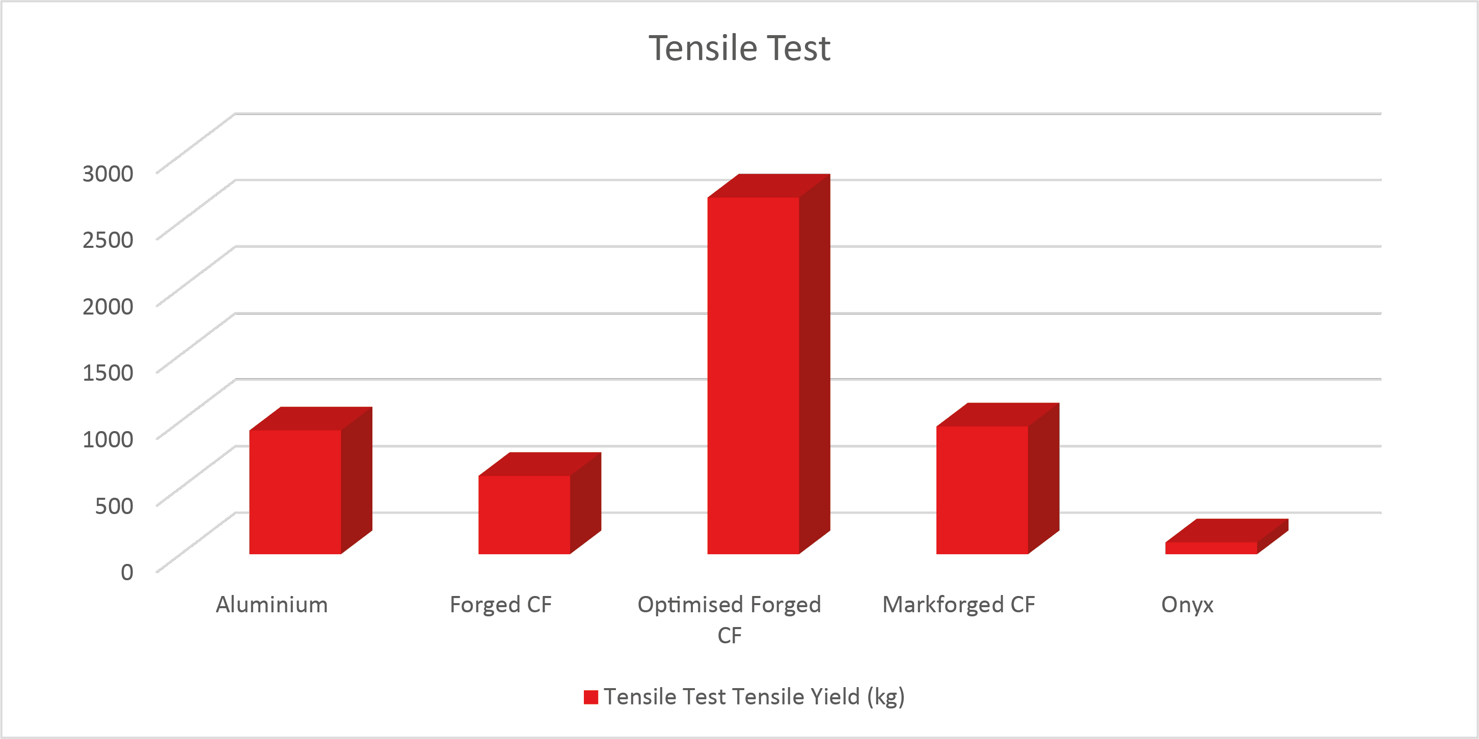
| Material | Tensile Yield (kg) | Tensile Yield (MPa) |
|---|---|---|
| Aluminium | 930 | 304 |
| Forged Carbon Fibre | 588 | 192 |
| Optimised Forged Carbon Fibre | 2680 | 875 |
| Markforged Continuous Carbon Fibre | 960 | 314 |
| Onyx | 89 | 29 |
Conclusion
Compression moulding chopped strand carbon fibre, in the way demonstrated in our forged carbon fibre demonstration, offers some significant advantages over cast/machined metal components as well as alternative composites moulding processes such a prepreg or resin infusion. The main advantages being the very low tooling and equipment costs, negligible waste/consumables, and the ability to reliably produce solid, fully moulded components. The disadvantage to this process however is its reliance on short strand (chopped tow) carbon reinforcement and the inevitable compromises on the mechanical performance resulting from its use.
The results of our investigation show that whilst a 'forged carbon fibre' component - reinforced using randomly oriented short strand carbon fibre - is indeed compromised in its mechanical compared to a continuous fibre reinforced component, the process still produces components with mechanical properties as good, or better, than cast aluminium and with the simple inclusion of some continuous fibre, can significantly outperform aluminium whilst still providing all the benefits of this cost-effective and fast-turnaround manufacturing process.
DISCUSSION (20)
Please share any questions or comments you may have about this video tutorial.
Firstly, I'll start by pointing out that your part is really very large for a forged carbon fibre process in the way we demonstrate. That's not to say it's not possible but we've not attempted to make anything of this volume using a forged carbon process.
Actually I think we've answered your question on fibre calculation fully already in the writeup on the forged carbon fibre video project page. As you already know the component's volume (from CAD) then your work is even easier.
This should cover the calculations at least. The final thing I would say would be to maybe start a bit smaller! It's always worth learning a process, making some mistakes and then possibly even changing your design for the large tooling once you've gained some experience.
From our own experimentation, you're likely to find that by the time you've reached the optimum density of fibre, vacuum infusion alone is not sufficient to drive the resin properly through the fibre. It's not helped by the fact that chopped carbon tow is still, by its nature, unidirectional fibres which tend to nest so close that they're difficult to infuse anyway (compared to woven fabrics where the resin can pass more easily through the 'nodes' where the weft and warp tows intersect). In reality, you would need more pressure than vacuum alone can provide (i.e. 1 bar) and so you'd need additional positive pressure to drive the resin through the reinforcement in a process that would be more akin to full-flown RTM. You could experiment with reducing the fibre fraction (i.e. packing less fibre into the cavity) in order to make the reinforcement more infusable but of course this will reduce the performance of the part correspondingly.
As for using a vacuum bag, rather than clamps, to apply even compression pressure to the mould halves, this might be possible but there are a couple of things to consider. Firstly, parts too large to realistically clamp probably aren't suitable candidates for a compression moulded forged carbon fibre process anyway, so how you best compress a large mould might be a slightly moot point. Secondly, an unforeseen consequence of using a vacuum bag to compress the mould halves might cause small air voids or pockets in the laminate to become much larger air voids/pockets in the laminate, effectively cavitating it. If the resin was successfully infused into the reinforcement under vacuum in the first place (problematic, discussed above) then this cavitation wouldn't be a potential problem but if the conventional process was followed and then the vacuum was only used to compress the mould then the fibre/resin mix is likely to have an amount of entrapped air which would expand under vacuum, potentially causing voids in the moulding.
If you do experiment with either of these two things, be sure to share your results and experiences!
It's quite difficult to give specific maximum and minimum dimensions for overall size, and wall thickness of parts because the shape and geometry of a component has a significant bearing on these other parameters, as does the mould strength and clamping compression force. To give some approximate indications we'd suggest that thickness should be at least 1mm and not more than 10mm. Overall component size really does come down to practicalities of the moulds and clamping arrangements but again, as a ballpark, maybe 500mm x 500mm. In terms of what scale of detail can or should be included, there's not really any constraints on this other than the fact that you'll probably need to do some sanding and fettling of the finished components and so any detail smaller than, say, 0.5mm should probably be avoided as it's likely to be rubbed out or softened by the finishing process anyway.
There is already a lot of mechanical data available for conventionally produced composite materials. However a direct comparison is not really possible as generally the methods have different applications. Eg the brake lever being a solid thick object is not ideal for conventional composite lay up, and thin conventional composite panels are not ideal for a forged carbon lay up by these DIY methods. So not easy to have a direct comparison that would be meaningful.
There are a number of different fibre reinforced filaments on the market with different base plastics and format for the fibres used. I agree it would be an interesting comparison video to test between the different filament types. Although from an Easy Composites perspective, it may well be a bit too in depth on the 3D printing side for a broad brushed comparison video. However there may well already be videos and reviews on social media for the various filament types in the 3D printing community.
Yes, absolutely. The strength of a composite part does not come from the tension the reinforcement is under when it is laminated. Pressure when manufacturing composite parts (like vacuum or autoclave) mainly serve to consolidate the reinforcement, reduce resin content (i.e. increase fibre fraction) and reduce void content. The purpose is not to put tension on the reinforcement.
Well, taking it to its logical conclusion, if the tow becomes long enough then you'll get to a point where you have undirectional reinforcement which would be very strong indeed and we know that milled carbon (um in length) does very little to benefit strength so there's obviously a strong correlation between strength and fibre length. However, there is also a practical consideration because we know that continuous fibre along doesn't work well in this compression moulding process because the fibres can't migrate and redistribute themselves inside the mould cavity and so there's a trade off and there will be an optimum fibre length for a given component. The size and shape of the mould will determine this to a large extent; in a smaller more complex mould (like the brake lever) even the 12mm tow is being prevented from randomly orienting by the geometry of the mould. In this case it's probably a good thing (steering more fibre to align in the zero axis) but on other occasions it might now be. For a larger moulding longer strands might be OK but such components are probably better made using woven cloth anyway.
Hi Rolf, it might be a little while before we return to any further testing on this material but there are indeed some other properties that would be interesting to get a better handle on, impact would be one of them. Temperature I think would be a lot easier to predict; whilst staying within the Tg of the resin system used, the results will remain pretty-much unchanged from the ambient results. For the IN2 resin system the Tg would be 92°C so under that, the material would behave as per the tests. If you need higher service temperature then a high temp resin system like our EL160 could be used, this can raise the Tg to over 160°C and also has even better mechanical properties than IN2. Certainly at this temperature you would have seen a collapse in the properties of the 3D prints but very little effect on the aluminium.
It's very rare you would ever want to increase the thickness of a component whilst maintaining the same amount of reinforcement. Since the reinforcement (like carbon) is lower density than the resin and brings by far the vast majority of the strength and stiffness, maintaining as high as possible a fibre fraction is always a good thing. For this reason, direct comparisons between a thicker, lower fibre-fraction laminate and a thinner, higher fibre fraction laminate are pretty moot. Broadly though, I'd expect more stiffness (flexural modulus) from the thicker laminate but a lower flexural strength. Overall tensile strength is easier to understand - the thicker component would have a slightly higher tensile strength because even resin would contribute something to the tensile strength and so if you're ignoring cross sectional area (which in your case, rather unusually - you are) then it would indeed take a slightly greater force to break the component if it was thicker with more resin. However, factoring for cross section you would significantly reducing the tensile strength.
Well, the considerations would be very similar to those governing the inclusion of unidirectional carbon fibre placement in a more conventional layup. The more unidirectional fibre you add, the stronger and stiffer your part will be in that direction, but at the expense of stiffness in other directions. For the forged carbon process, there would also be an upper limit to the amount of unidirectional tow you could add (in proportion to the chopped to) before there wasn't sufficient short strand tow in order to redistribute itself in the mould under pressure. Aside from that, if you have a specific direction of load then the more unidirectional tow you add in that direction the better!
There would still be many applications where ally would be a better material, as others have commented the failure mode of aluminium might still make it a better choice for a brake lever for example but then of course there's lots of situations where out-and-out strength-to-weight ratio is what you're after in which case carbon (in one form or another) is going to be the obvious choice.
Regarding the Markforged not beating aluminium, it's important to remember that it's a lot less dense and so the Markforged component on test is lighter than the aluminium. If you made it up to the same weight then it would be stronger (albeit slightly larger). If you look at the weights and densities of these materials (listed above) you can also compare their 'specific' properties (which factor for weight).
Hi, thanks for the post and thanks for placing an order with us. In terms of modelling the forged carbon fibre, the available data (and current level of understanding of the subject) is probably well short of being able to accurately model this material. Even our own data is not sufficient and would need doing to an established test standard in order to be useful in an FEA analysis. This might be a good subject for you or one of your colleagues to look further into!
No problem, you're welcome. I think we assumed that comparisons between the mechanical properties of various 3D print filaments had probably been pretty well covered already since these materials are widely available and their performance compared to each other is the source of plenty of debate and discussion. Nonetheless, I can see that a straight PLA/ABS print, tested on our gear under our conditions would be interesting, especially just to see whether the milled carbon in the Onyx really does much at all to improve a standard filament under these conditions. If we get chance, we'll look at adding this data to the report.
Thanks, glad you enjoyed it. Regarding providing the force in MPa/GPa, we've already done this. If you read through the above report, we've listed Kg and force. There's also additional information on weight and density so you can make 'specific' comparisons too.
Well, assuming you have to 3D print a mould and then mould your forged carbon component then a conventional 3D printed part (like the Onyx) would be much cheaper right from the start. In terms of the Markforged, the printers themselves are in the £20k/€25/$30 region and we don't have one so we paid to have the Markforged part printed. It cost over £100/€125/$150. You could certainly print the moulds in PLA and buy our whole Forged Carbon Kit (which could make 30 of these parts) for less money. In raw material costs, there's probably less than £1/€1.25/$1.50 worth of materials in the brake lever example.
Thanks for the comment Jeremiah. You raise a very interesting point actually; whilst it would indeed be interesting to see how the component compared if made using a wet-lay vacuum bag setup, it would actually be quite difficult to make the component in this way. The specific advantage of the forged carbon process is the ability to compression mould solid carbon fibre shapes. Such shapes are actually not very practical to make from a woven fabric and wet-lay vacuum bag. For starters, to achieve a solid 3D shape like this, we'd probably need to use a two-part compression mould anyway, meaning that even if we did use a woven fabric, the process would be more like compression moulding using a woven cloth. Our testing showed that use of continuous reinforcement in a matched-tool compression mould resulted in a high level of voiding (or at the very least very resin rich areas) because the continuous fibre can't migrate and redistribute itself in the mould cavity under pressure in the same way that the short strand chopped tow can. Nonetheless, I agree that it would be interesting to see and compare the result, even if we anticipate the component would be flawed.
Sudden impact can illicit a different response from materials which is why specific impact tests do also exist. We don't have an impact tester but we did fabricate an ad-hoc impact test for one of our previous material test videos (part of the 'Dark Ice Project' where we tested the impact strength of various materials like carbon fibre, Kevlar, Diolen, Dyneema etc.). Although it's a complex subject, you can predict a lot about the impact strength of a material from its ultimate strength, elongation properties and failure mode in tensile and 3-point bend tests.
Thanks for the feedback Adam, it's great to hear you enjoyed this investigation. The best way to include threaded metal inserts (or inserts in general) is during the moulding process if possible, this way they are encapsulated and retained by fibres as well as resin, which is stronger than bonding alone.
You're quite right that removing alignment/setting studs can be difficult. We would suggest using liberal applications of a thick film release agent, such as spray wax or even mineral jelly (i.e. Vaseline) on the studs. Also, if you can make the studs with flat spots so that they can be turned to crack them loose and twisted to extract them, that can help too.
LEAVE A COMMENT OR QUESTION
PRODUCTS USED IN THIS PROJECT
Although not necessarily an exhaustive list, the following tools and materials, supplied by Easy Composites, were used in this project.
The quantity shown below is the approximate amount used in the project rounded up to the nearest available kit size or quantity.
COMPONENT MATERIALS
DISCUSSION (20)
Please share any questions or comments you may have about this video tutorial.
Firstly, I'll start by pointing out that your part is really very large for a forged carbon fibre process in the way we demonstrate. That's not to say it's not possible but we've not attempted to make anything of this volume using a forged carbon process.
Actually I think we've answered your question on fibre calculation fully already in the writeup on the forged carbon fibre video project page. As you already know the component's volume (from CAD) then your work is even easier.
This should cover the calculations at least. The final thing I would say would be to maybe start a bit smaller! It's always worth learning a process, making some mistakes and then possibly even changing your design for the large tooling once you've gained some experience.
From our own experimentation, you're likely to find that by the time you've reached the optimum density of fibre, vacuum infusion alone is not sufficient to drive the resin properly through the fibre. It's not helped by the fact that chopped carbon tow is still, by its nature, unidirectional fibres which tend to nest so close that they're difficult to infuse anyway (compared to woven fabrics where the resin can pass more easily through the 'nodes' where the weft and warp tows intersect). In reality, you would need more pressure than vacuum alone can provide (i.e. 1 bar) and so you'd need additional positive pressure to drive the resin through the reinforcement in a process that would be more akin to full-flown RTM. You could experiment with reducing the fibre fraction (i.e. packing less fibre into the cavity) in order to make the reinforcement more infusable but of course this will reduce the performance of the part correspondingly.
As for using a vacuum bag, rather than clamps, to apply even compression pressure to the mould halves, this might be possible but there are a couple of things to consider. Firstly, parts too large to realistically clamp probably aren't suitable candidates for a compression moulded forged carbon fibre process anyway, so how you best compress a large mould might be a slightly moot point. Secondly, an unforeseen consequence of using a vacuum bag to compress the mould halves might cause small air voids or pockets in the laminate to become much larger air voids/pockets in the laminate, effectively cavitating it. If the resin was successfully infused into the reinforcement under vacuum in the first place (problematic, discussed above) then this cavitation wouldn't be a potential problem but if the conventional process was followed and then the vacuum was only used to compress the mould then the fibre/resin mix is likely to have an amount of entrapped air which would expand under vacuum, potentially causing voids in the moulding.
If you do experiment with either of these two things, be sure to share your results and experiences!
It's quite difficult to give specific maximum and minimum dimensions for overall size, and wall thickness of parts because the shape and geometry of a component has a significant bearing on these other parameters, as does the mould strength and clamping compression force. To give some approximate indications we'd suggest that thickness should be at least 1mm and not more than 10mm. Overall component size really does come down to practicalities of the moulds and clamping arrangements but again, as a ballpark, maybe 500mm x 500mm. In terms of what scale of detail can or should be included, there's not really any constraints on this other than the fact that you'll probably need to do some sanding and fettling of the finished components and so any detail smaller than, say, 0.5mm should probably be avoided as it's likely to be rubbed out or softened by the finishing process anyway.
There is already a lot of mechanical data available for conventionally produced composite materials. However a direct comparison is not really possible as generally the methods have different applications. Eg the brake lever being a solid thick object is not ideal for conventional composite lay up, and thin conventional composite panels are not ideal for a forged carbon lay up by these DIY methods. So not easy to have a direct comparison that would be meaningful.
There are a number of different fibre reinforced filaments on the market with different base plastics and format for the fibres used. I agree it would be an interesting comparison video to test between the different filament types. Although from an Easy Composites perspective, it may well be a bit too in depth on the 3D printing side for a broad brushed comparison video. However there may well already be videos and reviews on social media for the various filament types in the 3D printing community.
Yes, absolutely. The strength of a composite part does not come from the tension the reinforcement is under when it is laminated. Pressure when manufacturing composite parts (like vacuum or autoclave) mainly serve to consolidate the reinforcement, reduce resin content (i.e. increase fibre fraction) and reduce void content. The purpose is not to put tension on the reinforcement.
Well, taking it to its logical conclusion, if the tow becomes long enough then you'll get to a point where you have undirectional reinforcement which would be very strong indeed and we know that milled carbon (um in length) does very little to benefit strength so there's obviously a strong correlation between strength and fibre length. However, there is also a practical consideration because we know that continuous fibre along doesn't work well in this compression moulding process because the fibres can't migrate and redistribute themselves inside the mould cavity and so there's a trade off and there will be an optimum fibre length for a given component. The size and shape of the mould will determine this to a large extent; in a smaller more complex mould (like the brake lever) even the 12mm tow is being prevented from randomly orienting by the geometry of the mould. In this case it's probably a good thing (steering more fibre to align in the zero axis) but on other occasions it might now be. For a larger moulding longer strands might be OK but such components are probably better made using woven cloth anyway.
Hi Rolf, it might be a little while before we return to any further testing on this material but there are indeed some other properties that would be interesting to get a better handle on, impact would be one of them. Temperature I think would be a lot easier to predict; whilst staying within the Tg of the resin system used, the results will remain pretty-much unchanged from the ambient results. For the IN2 resin system the Tg would be 92°C so under that, the material would behave as per the tests. If you need higher service temperature then a high temp resin system like our EL160 could be used, this can raise the Tg to over 160°C and also has even better mechanical properties than IN2. Certainly at this temperature you would have seen a collapse in the properties of the 3D prints but very little effect on the aluminium.
It's very rare you would ever want to increase the thickness of a component whilst maintaining the same amount of reinforcement. Since the reinforcement (like carbon) is lower density than the resin and brings by far the vast majority of the strength and stiffness, maintaining as high as possible a fibre fraction is always a good thing. For this reason, direct comparisons between a thicker, lower fibre-fraction laminate and a thinner, higher fibre fraction laminate are pretty moot. Broadly though, I'd expect more stiffness (flexural modulus) from the thicker laminate but a lower flexural strength. Overall tensile strength is easier to understand - the thicker component would have a slightly higher tensile strength because even resin would contribute something to the tensile strength and so if you're ignoring cross sectional area (which in your case, rather unusually - you are) then it would indeed take a slightly greater force to break the component if it was thicker with more resin. However, factoring for cross section you would significantly reducing the tensile strength.
Well, the considerations would be very similar to those governing the inclusion of unidirectional carbon fibre placement in a more conventional layup. The more unidirectional fibre you add, the stronger and stiffer your part will be in that direction, but at the expense of stiffness in other directions. For the forged carbon process, there would also be an upper limit to the amount of unidirectional tow you could add (in proportion to the chopped to) before there wasn't sufficient short strand tow in order to redistribute itself in the mould under pressure. Aside from that, if you have a specific direction of load then the more unidirectional tow you add in that direction the better!
There would still be many applications where ally would be a better material, as others have commented the failure mode of aluminium might still make it a better choice for a brake lever for example but then of course there's lots of situations where out-and-out strength-to-weight ratio is what you're after in which case carbon (in one form or another) is going to be the obvious choice.
Regarding the Markforged not beating aluminium, it's important to remember that it's a lot less dense and so the Markforged component on test is lighter than the aluminium. If you made it up to the same weight then it would be stronger (albeit slightly larger). If you look at the weights and densities of these materials (listed above) you can also compare their 'specific' properties (which factor for weight).
Hi, thanks for the post and thanks for placing an order with us. In terms of modelling the forged carbon fibre, the available data (and current level of understanding of the subject) is probably well short of being able to accurately model this material. Even our own data is not sufficient and would need doing to an established test standard in order to be useful in an FEA analysis. This might be a good subject for you or one of your colleagues to look further into!
No problem, you're welcome. I think we assumed that comparisons between the mechanical properties of various 3D print filaments had probably been pretty well covered already since these materials are widely available and their performance compared to each other is the source of plenty of debate and discussion. Nonetheless, I can see that a straight PLA/ABS print, tested on our gear under our conditions would be interesting, especially just to see whether the milled carbon in the Onyx really does much at all to improve a standard filament under these conditions. If we get chance, we'll look at adding this data to the report.
Thanks, glad you enjoyed it. Regarding providing the force in MPa/GPa, we've already done this. If you read through the above report, we've listed Kg and force. There's also additional information on weight and density so you can make 'specific' comparisons too.
Well, assuming you have to 3D print a mould and then mould your forged carbon component then a conventional 3D printed part (like the Onyx) would be much cheaper right from the start. In terms of the Markforged, the printers themselves are in the £20k/€25/$30 region and we don't have one so we paid to have the Markforged part printed. It cost over £100/€125/$150. You could certainly print the moulds in PLA and buy our whole Forged Carbon Kit (which could make 30 of these parts) for less money. In raw material costs, there's probably less than £1/€1.25/$1.50 worth of materials in the brake lever example.
Thanks for the comment Jeremiah. You raise a very interesting point actually; whilst it would indeed be interesting to see how the component compared if made using a wet-lay vacuum bag setup, it would actually be quite difficult to make the component in this way. The specific advantage of the forged carbon process is the ability to compression mould solid carbon fibre shapes. Such shapes are actually not very practical to make from a woven fabric and wet-lay vacuum bag. For starters, to achieve a solid 3D shape like this, we'd probably need to use a two-part compression mould anyway, meaning that even if we did use a woven fabric, the process would be more like compression moulding using a woven cloth. Our testing showed that use of continuous reinforcement in a matched-tool compression mould resulted in a high level of voiding (or at the very least very resin rich areas) because the continuous fibre can't migrate and redistribute itself in the mould cavity under pressure in the same way that the short strand chopped tow can. Nonetheless, I agree that it would be interesting to see and compare the result, even if we anticipate the component would be flawed.
Sudden impact can illicit a different response from materials which is why specific impact tests do also exist. We don't have an impact tester but we did fabricate an ad-hoc impact test for one of our previous material test videos (part of the 'Dark Ice Project' where we tested the impact strength of various materials like carbon fibre, Kevlar, Diolen, Dyneema etc.). Although it's a complex subject, you can predict a lot about the impact strength of a material from its ultimate strength, elongation properties and failure mode in tensile and 3-point bend tests.
Thanks for the feedback Adam, it's great to hear you enjoyed this investigation. The best way to include threaded metal inserts (or inserts in general) is during the moulding process if possible, this way they are encapsulated and retained by fibres as well as resin, which is stronger than bonding alone.
You're quite right that removing alignment/setting studs can be difficult. We would suggest using liberal applications of a thick film release agent, such as spray wax or even mineral jelly (i.e. Vaseline) on the studs. Also, if you can make the studs with flat spots so that they can be turned to crack them loose and twisted to extract them, that can help too.
LEAVE A COMMENT OR QUESTION
100% SECURE
PAYMENT METHODS
Easy Composites EU B.V., registered in the Netherlands 73601195. All content copyright (C) Easy Composites Ltd, 2025. All rights reserved.