Need any help or advice?![]() +44 (0)1782 454499
+44 (0)1782 454499
Downloads (1)
| Forged Carbon Example Compression Moulds CAD Files |
VIDEOS IN THIS SERIES
This video is part 2 of a 4 part series: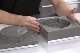

PRODUCTS USED IN THIS PROJECT
Although not necessarily an exhaustive list, the following tools and materials, supplied by Easy Composites, were used in this project.
The quantity shown below is the approximate amount used in the project rounded up to the nearest available kit size or quantity.
MATERIALS & CONSUMABLES


VIDEO TUTORIAL
How to Compression Mould Forged Carbon Fibre Components
In this composites video tutorial we demonstrate how to make solid, high performance, forged carbon fibre parts using a two-part compression mould.
In the tutorial we use a two-part compression mould made using a special epoxy casting resin and a three-part mould using a conventional FDM printer. Throughout the tutorial, we use the materials included in the Forged Carbon Fibre Development Kit from the Easy Composites.
WHAT YOU WILL LEARN
In this video tutorial we will create high-performance solid forged carbon fibre components using an ambient temperature compression moulding method. We work from 2 types of mould; a resin cast mould and a 3D printed mould.
This tutorial can be followed to make forged carbon fibre parts that will rival and even better the performance of metals in many applications and will cover the following topics:
- Compression mould design
- Suitable materials for mould construction
- Mould preparation and release agent application
- Calculating fibre and resin quantities
- Lamination/loading methods
- Mould compression methods
- Demoulding and finishing
INTRODUCTION
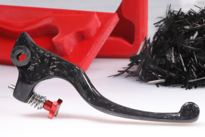
Forged carbon fibre is the term that has be adopted to describe short or ‘chopped’ strands of carbon fibre that are compression moulded in multi-part mould to create strong solid geometries that would not be practical using conventional composite processes.
There are 2 fundamental approaches to creating a forged carbon part, one is to use a pre-impregnated (prepreg) chopped tow material and mould this under heat and pressure, the other is to use a dry fibre and liquid resin system and mould under pressure but without heat. This project guide will focus on the latter, but the general principle and mould design principles are common with both material types.
Components manufactured with this method will have fully moulded faces, can have varying wall thicknesses, and will provide excellent mechanical performance that can be used in place of metals to reduce weight in many applications.
Fundamentals of Compression Mould Design
Compression mould tools will comprise of 2 or more parts which close together leaving a cavity where the component will be formed, in almost all circumstances the mould will be in a ‘block’ like format to provide strength and make the clamping or compression process practical.
The main consideration when designing tooling for this process is to include a telescopic section where the male tool acts like a piston inside a cylinder during closure, this allows room to load the uncompressed fibre and then during closure and excess resin will be squeezed out through the parting line but, being very closely fitting, the fibre cannot escape leaving you with the correct fibre to resin ratio. This telescopic or ‘piston-like’ element needs to be deep enough to allow the mould to start to close before disturbing the fibre, the exact size of this feature will vary depending on the mould shape and design but a general rule of having the feature extend at least 25% of the depth of the final component would be a good estimate. In the case of a 2-piece mould this feature will require a slight draft angle of 2-3 degrees to allow the mould to easily separate, in multi-part tooling it is often possible to design the mould so that it can separate away from a completely parallel ‘piston’ feature.
Mould Construction Materials
For volume production compression mould tools for this process would generally be manufactured from machined aluminium or steel, these would obviously offer excellent strength and durability but are expensive to produce making them less viable for short runs and prototyping.
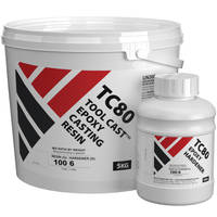
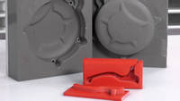
An alternative to billet metal tools is epoxy resin cast tooling in this project we will be using mould tools that have been cast in TC80 tool-cast resin, this example has been made by taking the castings from and existing injection moulded component but equally this could be cast from a conventional pattern or a 3D print. The resulting cast resin tools offer very good strength and durability and should be more that capable of producing tens if not hundred of components without wearing excessively. For more information on this tooling method please see our cast resin compression tools project.
Another tooling method that we will be using in this project is directly 3D printed PETG plastic tooling, whilst this doesn’t offer the strength and durability of solid mould tooling it has the advantage of being very cheap and rapid to produce and can be very useful for short runs and one-off prototyping, using this process with a 3D printed mould effectively allows you to produce components with genuinely high mechanical performance with no further specialist equipment or tooling. For this You will need a properly configured and setup FDM printer, in this project we have used the excellent Ultimaker S5 which with its pre-sets and intuitive user interface makes 3d printing easy, however any printer that is properly configured can, obviously, be used. If you are looking for advice on 3D printing, we would be happy to recommend our suppliers Dynamism. Although other filaments materials could be used, we have found that PETG offers great release properties and is accurate and easy to print making it a great choice. When printing compression moulds the infill should be at around 75% or higher to provide sufficient strength and stiffness during compression, also using a layer height of 0.15mm or less will provide a better surface for release.
Any customers wishing to experiment using the actual moulds shown in the video can download the forged carbon fibre compression mould CAD files which include the brake lever, paddle shift and conrod moulds in both IGES and STL files; note the STL files are are one file per mould section.
WHAT YOU WILL NEED
Materials and Equipment Needed for the Component
Release Agent
RW4 high build spray release wax is the recommended release system for ambient temperature compression moulding, this release agent performs particularly well when releasing rigid mouldings and castings from one another as it provides a thick barrier that is relatively soft and so can move a little during release if needed.
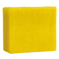
Filleting Wax
Filleting wax and/or plasticine is often useful for sealing threads on mould bolt threads or to infill and seal ejection holes in the mould.
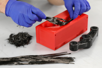
Chopped Tow
CT12 chopped tow is perfectly suited to this process, it has strands chopped at 12mm in length which offers a great balance of mouldability and strength.
Epoxy Resin
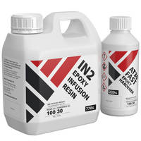
The IN2 resin has been found to offer excellent wet-out and flow in this process which is critical to successful moulding.
PROJECT BREAKDOWN
1. Prepare the mould
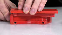
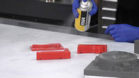
The moulds should be inspected and checked for any potential under-cuts or imperfections that may cause a problem with the release, in the case of a 3D printed mould you may find that shaving corners square with a blade will improve the accuracy of the closure. Once the moulds have been checked the release agent can be applied.
The RW4 spray wax is applied by spraying a thin film over the mould and allowing to dry for around 5-10minutes and then re-applying, typically 3 or 4 thin coats will provide a sufficient release, avoid trying to spray the wax in a single thick coat as this will take much longer to dry several thinner ones. The release agent should be applied to all faces and parting faces of the mould as the resin will drive into these during the compression stage.
Any ejection holes in the mould should now be sealed with filleting wax, these will need filling solid against a hard-stop as otherwise the pressure from the moulding process is likely to force then out. Any bolts in the mould should have the threads filled with the filleting wax to prevent them from being bonded into the tooling.

2. Calculate the quantity of fibre required
Accurately calculating the correct fibre loading for the mould is probably the single most important factor to get success with this process. The first stage in calculating the amount of fibre needed is to first know the volume of your finished component, if working from CAD this is very straight-forward and can be looked up from the properties window of a solid body. In the case of moulds that have been taken from an existing component, the volume is typically calculated by weighing the original component, referencing the density of the material that it is made from and then calculate the volume from that, for example, if we have an injection moulded part part that weighs 100g and is made from nylon 6 with 30% glass fibre (PA6 GF30) the density of this has been referenced to be 1.3grams per cubic centimetre so part weight / density = volume or 100 / 1.3 = 76.92.
Once the volume of the part is known the weight of the finished forged carbon part can be calculated, for quick calculation from a known volume you can use a simplified method of using 0.84g/cc for your fibre calculation but to better explain the reason it uses the following basic method: The density of forged carbon fibre is typically 1.4g/cc, so continuing our previous example density * volume = part weight so 1.4 * 76.92 = 107.69
Now that we have the final weight of the part we can calculate the amount of fibre required to achieve the optimal fibre to resin ratio which for this process is generally 60/40, (fibre/resin) by weight. So we can calculate the amount of fibre that we need by simply multiplying the finished part weight by 0.6 so in our example: 107.69 * 0.6 = 64.61g of CT12 fibre.
The required fibre should be accurately weighed out into a separate container that can be then used until emptied when laminating the part.
3. Calculate the amount of resin required
The amount of IN2 resin required can be quickly estimated by mixing a batch that is 25% heavier than the amount of fibre calculated so continuing with our example we have fibre weight 64.61 * 1.25 = 80.76g IN2 resin (mixed). This simple method will give you the excess resin that’s needed for this process much of this resin will be squeezed out in the process, the final component itself will have 43.08g of resin [107.69(final weight) – 64.61(fibre weight) = 43.08g] depending on the size and complexity of the part you are producing you may need additional resin in order to effectively laminate the part, this can be mixed as required during laminating.
The resin should only be mixed immediately prior to use, as with all epoxies accurate weighing mixing according to the instructions is essential.

4. Laminate the part
Laminating in this forged process is actually very similar to a typical wet-layup process; the mould should first have a thin coat of resin applied by brush, this will help to adhere the first layer of fibre and ensure that the entire surface has good wet-out, the fibre should be then lightly sprinkled over the surface and be consolidated and wetted out by stippling with a brush until the fibre is saturated and then repeated until the mould cavity is filled, some care must be taken to load the fibre evenly and approximately represent the final form of the component. Blunt tools or ‘dibbers’ will often prove useful to press the fibre into tight and detailed areas. You will find that during this process there will appear to be more fibre than will fit into the mould and the cavity with be over-filled, this is normal and will be forced into the cavity during compression.

5. Close and compress the moulds
Once all the fibre has been loaded into the moulds they can be closed and compressed. For smaller mould tools a bench vice or G-clamps will provide sufficient clamping pressure for larger tooling a pneumatic or hydraulic press may be appropriate. However, the compression is achieved it is important to close the tooling slowly particularly on more fragile moulds like those that have been printed, the reason for closing slowly in to allow time for the resin to flow in the cavity and any excess resin to flow out. If the mould was closed too quickly it can cause a hydraulic lock which would exert huge force on the moulds potentially damaging them. In most instances the tools can be clamped progressively over around 5 minutes. Once the tools fully meet or ‘bottom-out’ the part should be left under pressure until the resin system has cured.

6. Trim and finish
After Demoulding you will be left with some flash at the parting lines, this can be quickly removed with a sharp knife or abrasive paper, any release agent residue can be effectively removed with mould cleaner or similar solvent. Although these parts will have almost all of their potential structural performance straight from the mould a heated post-cure can be conducted to maximise the properties of the resin, please refer to the technical datasheet of the IN2 for more information.
The component would be completely serviceable straight from the mould but if the component is intended for a cosmetic application, a gloss clear-coated finish may be preferred, this can be sprayed with a 2k clearcoat or brush applied using XCR coating resin, to prepare for either of these finishes the parts should be keyed and flatted with 400grit wet and dry prior to application.
Another finishing option requiring no additional coating is to flat and sand the raw demoulded part to a fine 1200grit and then apply a car wax polish to leave a raw satin finish.
DISCUSSION (23)
Please share any questions or comments you may have about this video tutorial.
The volume of the Paddle Shifter is 28.6 cm³.
It's not something we have seen done. In essence you would need to design it more like an injection mould with a path for resin in and vent/vacuum paths for air and excess resin to go out. 3D prints may struggle under vacuum as well, limiting your options for mould materials.
Yes, potentially, but 1.5mm is very much towards the lower limit of wall thickness that you could realistically mould with this process. Whether you could successfully mould these ribs or flanges would come down to the specifics of their geometry (how deep are they for example), how you split the mould, and the shape of the overall moulding. You can probably imagine the factors that help or hinder the process, particularly the primary 'direction' of the compression as the mould halves are brought together. There would be some positions that these ribs or flanges could be in which would make them mouldable but there are other positions they could be in that would make them almost impossible to fill out and then compress successfully. If you gain some practical experience of the process on a simpler part then you'll likely gain a good insight for what's realistic and what's not before you attempt the more complex part.
It may be possible to do that. You would need to ensure careful placement for best effect. Also you may want to do some tests to failure to see if the failure method does anything undesirable when the two materials begin to behave differently at high loads.
It's great to hear you've taken the plunge! Let us know how you get on, it would be great to see some more parts that customers have made with the kit. We've seen some good examples already but it's fascinating to see the different components that people are making.
Yes, there might be. Firstly, depending on the plastic you've used for the 3D print and the type of high-build primer that you use, you might find that the paint reacts with, or at least softens slightly, the 3D print so I'd recommend testing this first. Secondly, you might also encounter problems getting the epoxy component to release properly from the mould if you've surfaced it with primer. This is by no means for sure but the solvent in spray paints, including primers, often adversely affects the release agent (in this case the spray wax) which could cause the component to either stick in the mould, or, just as likely, the primer to come off the mould but be stuck to your part. Again, if you want to go down this route then plan to test it first.
If you do want to improve the surface of your mould in a more reliable way, consider using a specialist epoxy coating resin, like our XCR Epoxy Coating Resin, which can be applied to 3D prints and creates a reliable, fully compatible shell that you'll have no problem releasing from. You'll see us applying this resin to a 3D print in our drone shell tutorial.
Entirely depends on the resin system used. Some plastics, like PETG, are naturally able to release from resins. If the plastic resin used is a type of plastic that naturally releases, then the smoother finish of resin printed parts would likely mean a slightly easier release.
An insert is bonded into the lever to support the thread. Forged Carbon fibre is not strong enough to support a thread being cut into it.
It is a higher viscosity so it may not be as effective especially for bigger parts. You could gently warm the resin and mould but you have to be careful of the exothermic runaway that could occur. Certainly the compression phase will need to be slowed down to allow the thicker resin to compress and excess squeeze out.
No, the resin is quite low viscosity which helps avoid air entrapment and also the compression itself helps squeeze out any remaining air and excess resin.
Hi Justin, no stupid questions here! Yes, you could do this with glass fibre but - of course - you'd need chopped glass rovings (instead of chopped carbon tow). After that, the process would be identical (although the density of glass is greater than carbon so your volume calculation would need adjusting by the difference). In terms of performance, a glass reinforced part would, as you'd guessed, be stronger than an unreinforced plastic but not as strong (or stiff, depending on your priorities) as aluminium or carbon.
No, unidirectional carbon fibre is almost the opposite thing. Unidirectional reinforcement is continuous fibre reinforcement with all the fibres running in the same direction, it's used when you know the orientation that you want to add the most strength in. The chopped tow we're using here is relatively short strands of carbon fibre in random orientation, providing strength in all directions. The chopped tow is critical to this application though because the short strands allow the reinforcement to 'flow' and redistribute itself inside the mould when it's compressed.
In principle it might be possible and we haven't tried it so can't say for sure but our concern would be that the compression moulding process very much relies on the ability of the reinforcement to move around relatively freely and redistribute itself around the mould. Woven cloth, being made of continuous fibres, would be unable to move in this way and so at least some of the reinforcement you're adding wouldn't be able to do this redistribution. However, for a single ply, if there was a reasonable amount of chopped tow behind in, might work out fine. It would certainly need to be limited to flat areas though. If you give it a try, let us know how you get on.
Well, at 80 parts per day using a vacuum bagged process I'm assuming you have more than one tool? If so, multiplying the tools would also increase production capacity using a compression moulding process. Additionally, there would be lots of ways you could speed up production using this compression moulding process; you'd need rigid (cast or billet machined) tools but you could heat the tools once the compression was done and cure the resin off in around an hour. You're never going to get to the 10 parts per hour you mentioned but, outside of some very sophisticated hot-press processes - I really don't know of much in composites than can cycle at that rate.
Assuming we're talking about a Honda *car* engine valve cover then I'd say you're probably past the scale and shape that this process is best suited for. That's not to say it wouldn't be possible to make something this large but it would probably be easier and better to make it using a conventional single-sided mould and use either prepreg, resin infusion or vacuum bagging for the layup.
An autoclave is doing two things, it's providing pressure and heat. If you're using 'prepreg' carbon fibre to make your parts then this means that the resin is already combined with the carbon fibre and it's already been mixed with its hardener (that's why they're stored in a freezer) but to cure the resin you *need* heat, this means that prepregs must be cured in an oven or autoclave. The additional pressure of an autoclave help to consolidate the reinforcement, increasing the fibre ratio and reducing the void content. This is also what happens with compression moulding where - if done right - the pressure could be equal to or higher than the pressure in an autoclave.
If you're using a resin system designed for ambient temperature cure and you're applying pressure equivalent to an autoclave then the mechanical properties of the resulting component would be very similar. Ultimately, the use of an autoclave is often more of a practical consideration (i.e. what's the best way to make this particular part/shape?) than it is a matter of it outright being a superior manufacturing process in terms of the performance of the component.
LEAVE A COMMENT OR QUESTION
Downloads (1)
| Forged Carbon Example Compression Moulds CAD Files |
PRODUCTS USED IN THIS PROJECT
Although not necessarily an exhaustive list, the following tools and materials, supplied by Easy Composites, were used in this project.
The quantity shown below is the approximate amount used in the project rounded up to the nearest available kit size or quantity.
MATERIALS & CONSUMABLES
DISCUSSION (23)
Please share any questions or comments you may have about this video tutorial.
The volume of the Paddle Shifter is 28.6 cm³.
It's not something we have seen done. In essence you would need to design it more like an injection mould with a path for resin in and vent/vacuum paths for air and excess resin to go out. 3D prints may struggle under vacuum as well, limiting your options for mould materials.
Yes, potentially, but 1.5mm is very much towards the lower limit of wall thickness that you could realistically mould with this process. Whether you could successfully mould these ribs or flanges would come down to the specifics of their geometry (how deep are they for example), how you split the mould, and the shape of the overall moulding. You can probably imagine the factors that help or hinder the process, particularly the primary 'direction' of the compression as the mould halves are brought together. There would be some positions that these ribs or flanges could be in which would make them mouldable but there are other positions they could be in that would make them almost impossible to fill out and then compress successfully. If you gain some practical experience of the process on a simpler part then you'll likely gain a good insight for what's realistic and what's not before you attempt the more complex part.
It may be possible to do that. You would need to ensure careful placement for best effect. Also you may want to do some tests to failure to see if the failure method does anything undesirable when the two materials begin to behave differently at high loads.
It's great to hear you've taken the plunge! Let us know how you get on, it would be great to see some more parts that customers have made with the kit. We've seen some good examples already but it's fascinating to see the different components that people are making.
Yes, there might be. Firstly, depending on the plastic you've used for the 3D print and the type of high-build primer that you use, you might find that the paint reacts with, or at least softens slightly, the 3D print so I'd recommend testing this first. Secondly, you might also encounter problems getting the epoxy component to release properly from the mould if you've surfaced it with primer. This is by no means for sure but the solvent in spray paints, including primers, often adversely affects the release agent (in this case the spray wax) which could cause the component to either stick in the mould, or, just as likely, the primer to come off the mould but be stuck to your part. Again, if you want to go down this route then plan to test it first.
If you do want to improve the surface of your mould in a more reliable way, consider using a specialist epoxy coating resin, like our XCR Epoxy Coating Resin, which can be applied to 3D prints and creates a reliable, fully compatible shell that you'll have no problem releasing from. You'll see us applying this resin to a 3D print in our drone shell tutorial.
Entirely depends on the resin system used. Some plastics, like PETG, are naturally able to release from resins. If the plastic resin used is a type of plastic that naturally releases, then the smoother finish of resin printed parts would likely mean a slightly easier release.
An insert is bonded into the lever to support the thread. Forged Carbon fibre is not strong enough to support a thread being cut into it.
It is a higher viscosity so it may not be as effective especially for bigger parts. You could gently warm the resin and mould but you have to be careful of the exothermic runaway that could occur. Certainly the compression phase will need to be slowed down to allow the thicker resin to compress and excess squeeze out.
No, the resin is quite low viscosity which helps avoid air entrapment and also the compression itself helps squeeze out any remaining air and excess resin.
Hi Justin, no stupid questions here! Yes, you could do this with glass fibre but - of course - you'd need chopped glass rovings (instead of chopped carbon tow). After that, the process would be identical (although the density of glass is greater than carbon so your volume calculation would need adjusting by the difference). In terms of performance, a glass reinforced part would, as you'd guessed, be stronger than an unreinforced plastic but not as strong (or stiff, depending on your priorities) as aluminium or carbon.
No, unidirectional carbon fibre is almost the opposite thing. Unidirectional reinforcement is continuous fibre reinforcement with all the fibres running in the same direction, it's used when you know the orientation that you want to add the most strength in. The chopped tow we're using here is relatively short strands of carbon fibre in random orientation, providing strength in all directions. The chopped tow is critical to this application though because the short strands allow the reinforcement to 'flow' and redistribute itself inside the mould when it's compressed.
In principle it might be possible and we haven't tried it so can't say for sure but our concern would be that the compression moulding process very much relies on the ability of the reinforcement to move around relatively freely and redistribute itself around the mould. Woven cloth, being made of continuous fibres, would be unable to move in this way and so at least some of the reinforcement you're adding wouldn't be able to do this redistribution. However, for a single ply, if there was a reasonable amount of chopped tow behind in, might work out fine. It would certainly need to be limited to flat areas though. If you give it a try, let us know how you get on.
Well, at 80 parts per day using a vacuum bagged process I'm assuming you have more than one tool? If so, multiplying the tools would also increase production capacity using a compression moulding process. Additionally, there would be lots of ways you could speed up production using this compression moulding process; you'd need rigid (cast or billet machined) tools but you could heat the tools once the compression was done and cure the resin off in around an hour. You're never going to get to the 10 parts per hour you mentioned but, outside of some very sophisticated hot-press processes - I really don't know of much in composites than can cycle at that rate.
Assuming we're talking about a Honda *car* engine valve cover then I'd say you're probably past the scale and shape that this process is best suited for. That's not to say it wouldn't be possible to make something this large but it would probably be easier and better to make it using a conventional single-sided mould and use either prepreg, resin infusion or vacuum bagging for the layup.
An autoclave is doing two things, it's providing pressure and heat. If you're using 'prepreg' carbon fibre to make your parts then this means that the resin is already combined with the carbon fibre and it's already been mixed with its hardener (that's why they're stored in a freezer) but to cure the resin you *need* heat, this means that prepregs must be cured in an oven or autoclave. The additional pressure of an autoclave help to consolidate the reinforcement, increasing the fibre ratio and reducing the void content. This is also what happens with compression moulding where - if done right - the pressure could be equal to or higher than the pressure in an autoclave.
If you're using a resin system designed for ambient temperature cure and you're applying pressure equivalent to an autoclave then the mechanical properties of the resulting component would be very similar. Ultimately, the use of an autoclave is often more of a practical consideration (i.e. what's the best way to make this particular part/shape?) than it is a matter of it outright being a superior manufacturing process in terms of the performance of the component.
LEAVE A COMMENT OR QUESTION
100% SECURE
PAYMENT METHODS
Easy Composites EU B.V., registered in the Netherlands 73601195. All content copyright (C) Easy Composites Ltd, 2025. All rights reserved.