Need any help or advice?![]() +44 (0)1782 454499
+44 (0)1782 454499
Downloads (1)
| CAD Files for Drone Arm and Linkage Moulds |
VIDEOS IN THIS SERIES
This video is part 4 of a 4 part series: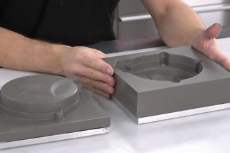
PRODUCTS USED IN THIS PROJECT
Although not necessarily an exhaustive list, the following tools and materials, supplied by Easy Composites, were used in this project.
The quantity shown below is the approximate amount used in the project rounded up to the nearest available kit size or quantity.
MATERIALS & CONSUMABLES


VIDEO TUTORIAL
Forged Carbon Fibre Mould Design and Strength Optimisation
Extended length version with full CAD walkthrough
This is the extended length version of our video tutorial on mould design and strength optimisation for forged carbon fibre parts and includes over 10 minutes of additional detail on CAD techniques for compression mould design.
This video is a follow on from our earlier tutorial How to Compression Mould Forged Carbon Fibre Components and expands on mould design best-practice and strength optimisation using strategic placement of long strand carbon tow, in conjunction with the short strand chopped tow.
INTRODUCTION
Since our first video on compression moulding forged carbon fibre, many enthusiasts have used this method to create a variety of components. The aim of this video is to cover in more detail some areas not covered originally.
Specifically we are going to go into more detail on how to design a successful mould for the forged carbon process. This is going to be demonstrated in CAD, and as in previous videos, this is aimed at those who have some CAD experience and will focus on the specific features and tools needed to create a successful mould. Although shown in Fusion 360, most of these tools and features can be created in other CAD packages in a similar way.
The second topic to be covered will be the use of longer strands of carbon fibre tow to optimise the performance of the forged carbon part. This is especially useful for parts which are loaded in one direction where the additional strength of the correctly orientated carbon fibre tows can add considerable strength compared to the standard forged carbon parts.
TUTORIAL BREAKDOWN
1. Mould Design Initial Considerations
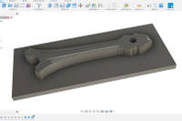
We start with a model of the part a mould is being made for. In this case, a model of the arm we want to replicate. The first step is to consider the best orientation to conduct the compression for the forging. On a relatively flat part like this, its flat plane is the ideal orientation to make sure the compression aspect occurs over the shortest distance possible.
On this model, the first thing to do is delete some of the small 3mm holes. Although these could be left in and a dowel pin used, it is quite tricky to do and it will be much easier to make as a blank then machine the holes in afterwards. Once deleted, the next step is to create a bounding box for the tool itself.
2. Creating the Piston aspect of the Tool
To do this, use the sketch feature to make the box around 15mm bigger than the outer dimensions of the part. This will ensure the mould tool has sufficient strength and stiffness for the compression process. Dimensions are not too critical for this stage.
Next, selecting the outline of the component, the project tool is then used to extrude the top part of the piston into the tool. For smaller tools about 6mm is fine, bigger tools may want as much as 15 or 20mm. This is then going to be used to create the profile by creating an offset using the sketch of the part outline. This is done to help load the material into the mould. A rough rule of thumb is to have the piston 2-3 times the depth of the part. In this case about 18mm of travel.
To add the piston itself, we will extrude from the sketch of the part outline upwards to the tool body we have created. Once the new body has been created, the original part can be hidden and the two tool components combined.
3. Modelling Lower Section of the Tool
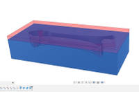
Now the top part of the tool is complete, the rest can be drawn. This is started by selecting the top face and extruding through both the tool and the part to create a piece of stock. Again, about 6mm through is about right to create a thick enough tool. The wire frame view mode will help you see what is going on in relation to the parts and tools.
The model and the upper tool is then used to cut the cavity into the lower tool. Using the combine tool, select the new body then select and subtract the upper tool and part from the lower mould stock. We want to keep the tools we are cutting with so tick the "keep tool" box. Once executed, the upper tool and part can be hidden revealing the lower tool with the exact cut out required.
4. Adding Splits
The lower mould needs to have splits added to it as, with parallel sides, it would not release due to the lack of draught angle. By splitting the mould into pieces, it makes extracting the component very easy. In this specific case, due to the Y shape feature, a simple split down the middle would not work so a third piece to the split mould is needed to allow it to release.
When designing a compression mould, if you have any doubt about the release of a component, then its best to add extra elements to the mould to ensure a good release. This is especially important with printed moulds as they are more fragile and easy to break. Its a common error to be a little bit over optimistic with release and cause problems extracting the part from the tool.
To create the splits, first create a sketch on the top surface of the body. Concentric circles are drawn on the holes so that they can be used to run the split line perfectly through the holes. A split line is then drawn through the holes to one end of the mould and then another line to the back of the component. Extra lines are drawn to create the split lines for the third piece. Then the outline of the part is projected onto the sketch and the trim tool used to remove any unwanted elements.
To create the actual split, the Split Body tool is used. Firstly we are creating the piece at the back of the component, so select the body and the drawn line as the splitting tool and create the split. The splitting function is repeated for the remaining split line using the same tool and the central line on the sketch as the split line. This now leaves us with the necessary three split parts.
To hold the elements together, some 6mm holes to enable the pieces to be clamped together. The holes are sized to 6.2mm and, using the wireframe view, placed to ensure they cut only through the stock itself not the cavity. As 3D printed moulds are not that stiff, keep the spacing down to 50-75mm to ensure the mould parts cannot open up or distort.
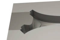
5. Adding Chamfers and Inserts
The next feature to add is a chamfer between the mould elements. This is to aid release by providing a feature for putting a wedge to aid separating the mould parts. To do this, the chamfer tool is selected and used to highlight all the edges that need a chamfer. The chamfer will be sized at 3mm to give enough room for the wedge. The chamfer is continued around the perimeter of the tool to allow the top tool to also be easily separated.
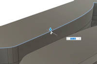
The next chamfer to add is around the perimeter of the mould cavity. This is so that when closing the tool, there is a small bit of lead in for the upper tool to help them locate easier as the clamping force is applied. The edge of the tool void is selected and the chamfer tool used to create the chamfer, this time using 1mm horizontally and 2mm downwards.
The next stage will be allowing for the installation of a threaded insert. Although forged carbon can have a thread formed in it, it is not a strong thread, so for all but the lightest work applications, it is better to use a metal insert for both durability and strength. The simplest way, in a case like this, is to use brass knurled inserts available from a variety of sources.
To include the insert, they need to be bolted into the mould so that they can be laminated around and locked into place. To do this, we will use a bolt through a hole in the mould to hold it in place. A hole can be simply extruded through the mould to give a location for the bolt to go through.
Now putting the tools back together and doing a cross sectional analysis, we can see that the tools are size on size with no gap. If there is any inaccuracy in the printing, this may mean it is hard to get the tools to fit together. So a small amount of material needs to be removed to account for this. To do this, a sketch is created and the outline of the part selected. An offset is created to be used to cut the tool. Generally about 0.1mm is sufficient. This will allow the tools to fit together easily and also allow an escape path for the excess resin used in the process. If the offset is too big, the risk is that fibres can run up into the gap. Once the sketch is complete, the extrude tool is used to cut the 0.1mm off the tool.
The tool is now complete. One feature not mentioned is the 8mm hole running throughout the mould. A dowel pin will be inserted here and the process carried out around it. Once cured, the dowel pin can be driven out leaving a precisely located perfectly sized hole in the finished part.
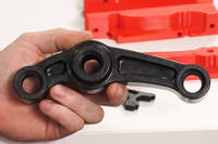
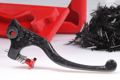
6. Forged Carbon Linkage Example
This substantial linkage arm is the next part we will focus on as it has some unique features to consider. Firstly the hole in this part has a stepped internal feature to act as a bearing journal. This means a simple straight dowel pin cannot be used. This means we will need to use a split bush. This has a large tapered section in the middle, with a generous draught angle, which allows the bush to be split and help with its release. Although the parallel section is not ideal, it is short, so with a high build release wax it should be possible to extract the bush from the part. The bushes are inserted into the mould and laminated around as would be done with a straight dowel.
Looking at the rest of the tooling, it is conceptually very similar to the previous example and was drawn in CAD in much the same way with similar features. The lower part of the mould is in two pieces which may look ambitious from a release perspective. Due to the recesses in the component, ordinarily trying to release the part sideways would lock the part into the mould. However, the way we would extract this part is to remove the dowel pins, Then extract the upper part of the tool easily enough. The component can then be extracted upwards and released from the mould.
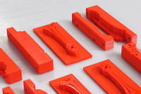
7. 3D Printing the Moulds
Now that the CAD work is complete, the next stage is to use the models to print the moulds. The models can then be run through a slicer software to make the code for the 3D printer. Settings wise, although you can use many different materials for these moulds, we find PETG offers the best balance of strength, ease of printing and release from epoxy.
Resolution wise, these will be printed at a 0.1mm layer height. Although quite fine, this will improve the surface finish and also reduce the chance of the part mechanically locking into the mould. These moulds need to be strong to withstand the clamping force used during the compression moulding and hence a high wall count of 5 loops is used along with a 75% infill ratio.
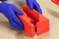
8. Mould Preparation
Onto the process itself, We will be covering the fundamentals relatively quickly as they are well covered in our previous video: How to Compression Mould Forged Carbon Fibre We would recommend watching it as it will give the complete picture of the process involved.
The materials used are seen in our Forged Carbon Fibre Development Kit which is a great way to get started with enough materials to do a kilo of the forged carbon material. A recent addition to the kit is 50g of Carbon Fibre Tow to enable you to experiment with the optimisation process that we will show and focus on shortly.
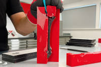
The first stage is to apply the release agent. In this case, we are using the RW4 Release Wax spray as the release properties it offers and ease of application are difficult to achieve with other materials. When spraying, ensure that all sides of the print are evenly covered, leaving split moulds like this in their separate pieces for the release wax application. A total of 2 spray applications will be needed, leaving 15 minutes drying time between each coat.
While the RW4 is drying, the bolts we are using to clamp the moulds together can be coated with the soft filleting wax. The purpose of this is to stop the resin sticking to the bolts during the process. The wax ensures that the bolts will be easily removed when it comes to demoulding.
The knurled brass inserts can now be positioned in the mould and held in place with a bolt. The bolt is coated in filleting wax in the same way and then bolted into position. The dowel pins, which have been coated in RW4 Release wax, are then dropped into place. These are then dropped into the backing plates so it can sit flat with the pins in place.

9. Fibre Optimisation & Preparation
Getting the fibre loading correct for the mould is one of the most critical aspects of the process. This cannot be done by eye and needs careful calculation to get right. First of all, the volume of the parts is needed. Consulting the CAD model, we can determine the volume of the parts, in this case 11.24cm³ for the front arm and 12.97cm³ for the longer rear arm.
Now we need to calculate the weight of the finished part, so taking these volumes, we multiply them by 1.4 (the typical density of a finished forged carbon part) to give the overall weights. This gives us 15.74g for the front arm and 22.04g for the rear arm. The forged carbon part will use a fibre to resin ratio of 60:40 (by weight) thus to work out the amount of fibre needed, we can multiply the total weights by 0.6. This gives a fibre loading of 9.44g and 10.89g respectively.
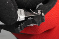
We could just use the standard chopped tow and achieve similar performance to the original arm. Looking at the original arms, they are a 5mm thick carbon fibre sheet. This is made with fibres running down the length and across the width. Burning out the resin matrix allows us to precisely see what the multiple plies of the layup are. The uni-directional fibres running down the length of the arm are contributing strength in an optimal way, while the fibres running perpendicular are not adding anything to the strength. A forged part has randomly orientated strands which act in an almost isotropic way.
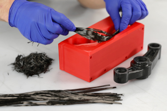
Now we can consider how to optimise the strength of the part, In this case we can replace some of the chopped tow with long continuous fibres to bias the strength in the direction we need it. In the case of this arm, that is down its length. It is not possible to replace all the chopped tow with continuous fibres as it does not flow resin as well around the mould cavities, so in this case we are going to replace 30% of the chopped tow with the continuous fibres. This equates to 2.8g of continuous fibre, which can be cut to length and then weighed, also weighing out the chopped tow to make up to the full 9.44g total fibre loading.
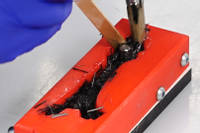
10. Loading the Fibre and Resin
Dividing the chopped tow into two equal piles ensures there is an equal amount for each side of the continuous fibre. At this stage we can now measure out and mix the resin needed. The process typically uses 25% more resin than the weight of the fibre. However, when working on very small parts like this arm, you will often mix a little bit more resin to allow for wastage in the brush and cup. So In this case we are going to mix 20g of resin and hardener combined.
The first pile of chopped tow is then added to the mould in batches, wetting it out with resin. The long continuous tows can then be added to the mould in the direction needed for the required strength. These can either be wetted out as placed into the mould, or wet them out before placing into the mould. Both are perfectly valid methods and can be used as needed to suit the part being made. This can be done in a simple linear fashion, as with this arm, or looped around features such as bolt holes and dowel pins. Once this is done, the remainder of the chopped tow can be added to the mould wetting out with more resin as you do so.
11. Compression
Once the fibres have been loaded into the mould we can then insert the top of the mould and get ready to compress. When inserting the top part of the mould, take care to minimise trapping too many fibres. A backing plate is then added and the mould can be compressed using a bench vice, clamps or a press.
It is essential to apply the clamping force slowly in stages. If you apply the force too quickly, you risk damaging the relatively fragile 3D printed moulds. Once the tool has fully bottomed out and closed, the tool can be left for 24 hours for the resin to fully cure.
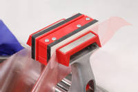
12. Demoulding
Now that the parts have cured, we can now get them demoulded. The backing plates are removed first, followed by unbolting any bolts and driving out any dowels. Wedges can then be used to separate the mould pieces to release the parts themselves.
13. Finishing the Parts
The flash lines can be quickly and easily be removed by scraping with a blade. If the cosmetic finish is not important, these parts can now be put into service. At this stage, the finish will be the same as the 3D printed mould, so featuring the layer lines and texture. These can be removed by sanding lightly to smooth the part out, then finishing by coating in our XCR Epoxy Coating Resin or by using a spray clear coat to enhance the finish. A quick method that works well is to sand to 1200 grit then apply two or three coats of S120 Board sealer to the part. This will both seal the surface and enhance the appearance.
At this stage any machining or finishing can be done. In this case, the M3 holes for the motor mounting can be drilled using a standard drill and 3D printed drilling jigs for accuracy.
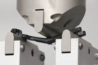
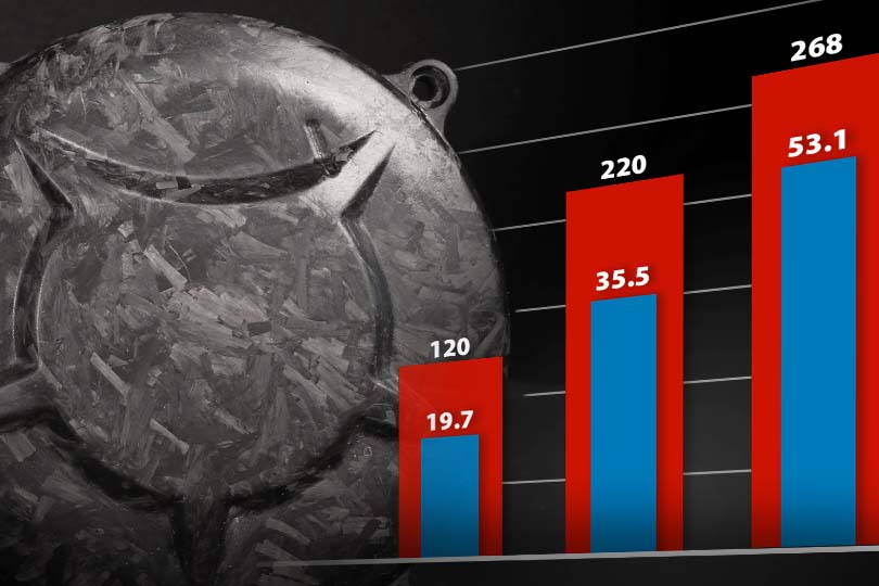
14. Strength Testing
In theory, these forged carbon arms should perform similarly to the original ones made from flat carbon sheet. We have the advantage that we are not constrained by simple 2D geometry so have been able to add in extra features. In this case, a cable recess has been added as well as integrating the skid. These arms have a slightly smaller cross sectional area than the original arms so although not directly 100% comparable, we are going to test them to see how they perform and compare to the originals.
On the graph, you can see that the forged carbon arms are slightly stiffer than the originals. However pushing them to the point of failure, it does break around 15% sooner than the original arm. This shows that the forged carbon arm is slightly stiffer but slightly less strong compared to the original. This is likely down to the smaller cross sectional area and it should be possible to get this strength back by adding more continuous fibres to the moulding. With that said, these arms should definitely do the job. All that remains is to attach the arms to the drone and take it for a test flight.
DISCUSSION (17)
Please share any questions or comments you may have about this video tutorial.
These were fitted to a GEPRC Mk5 drone model.
Yes there is. The IN2 resin used in the video comes with a Fast or Slow hardener. When ordering the resin, you can choose which hardener speed you prefer. In the videos, we use the Fast hardener.
The Drone arm was originally drawn in Fusion 360 so uses fusion's propriety file format when saved. It can be exported into different file formats to suit the slicing software used with the 3D printer of your choice.
Great question, yes the high infill will certainly help the thermal mass and conductivity and reduce the likelihood of thermal runaway, in this particular process around 8mm of cross-section depth works with the IN2 and fast hardener, you can probably double this with the slow hardener, beyond that then switching to aluminium tooling or experimenting with other cooling methods like you mention might allow even thicker parts to work.
Thanks for the question, for some shapes that would be possible but because of the varying thickness and shapes on this part the fibres need to be able to migrate around the cavity and that's where the short tows come in, I'm sure i could have pushed it to around 60% long tow and still had good results though.
The carbon fibres in a carbon composite are the metal wires in concrete; i.e. they are providing the tensile strength to the material, in the same way that the resin provides the 'matrix' that holds the tensile reinforcement in position like concrete does to the rebar. Since carbon fibre is must stronger in tension (weight-for-weight) than any metal, it's already adding the maximum possible strength (for a given weight), adding metal would proportionally increase the weight and/reduce the strength.
Good question and well explained. It's interesting that you've been experiencing air entrapment, and interesting that it's predominantly on the piston side. I can picture how, if it was going to occur, that's where it would happen. Is there any possibility that you're underloading the cavity? Although air pockets could occur (especially in some geometries) the clamping pressure is normally sufficient to overcome them. One possibility (not that we've needed to do this ourselves) might be to introduce a 'vent' hole into the mould design (or just drill one in now) to the area where the air entrapment is occurring. It would need to be very small in diameter to prevent reinforcement from escaping but might help. As for vibration, I honestly don't know if that would help or not, it's not something we've tried. If you do give it a go, let us know whether it helps.
You could post cure these parts to improve mechanical and temperature resistance properties. Given that we used 3D printed moulds doing an 'in mould' post cure to support the parts would be limited to fairly low temperatures.
It's never a bad idea because it will give you a better finish and can help with release but we do tend to find that the RW4 gives enough build to ensure a pretty reliable release, so I guess it comes down to whether you want that slightly better finish straight out of the mould. If you're making multiple parts from the same mould then it would make more sense to improve the mould with some light sanding and then have less work to do on each part, but if you're only making one part then it doesn't really matter whether you sand the mould or the part.
Thanks for the comment, it really depends on the application, but for a typical suspension linkage you would generally be fine running without an insert with some bearing fit compound.
Thanks for the question, composites in general are very good when it comes to resisting stress fatigue, in most applications they should greatly outperform metals.
That's a very good question because, as you've pointed out, the UD fibres would have more influence the further out they were. As you've kind of guessed, the reason is really a practicality of the forged carbon process. It's only the short strand fibres that are properly mobile and will 'flow' into the mould's surface detail reliably, which is why we opted for short strand on the surface and then the long strands could happily sit in the middle of the laminate. That said, this is a relatively new process even to us and it's quite possible that we could have put UD fibres closer to the outside faces of the component and still got good results. If you experiment with this yourself, please do share your experience and results.
The main limitation in terms of heat tolerance comes from the 'Tg' (glass transition) temperature of the resin that's used. In the case of the IN2 epoxy resin we include in the kit, this has a maximum service temperature of around 75°C (167°F) which wouldn't really be suitable for high temperature applications. Although there might be some compromises in terms of viscosity, you could switch the IN2 to something like our EL160 to get the maximum service temperature up to about 170°C (338°F).
We almost always use PETG. Everything you see in the video is PETG.
The actual shrinkage will vary depending on factors like thickness and cure temperature but for the majority off applications it is negligible (maybe <0.5% linear) an so you can discount it, I would say that the accuracy of the print will be a bigger factor in most cases.
No, we've not done that. With a part so small, the material costs would be pretty low in both cases, meaning that the machining time, or cost of mould production, would be the bulk of the cost. In which case, it really makes a big difference how much you're getting charged for machining or printing, or your own time, making a direct comparison quite tricky. Not that it's the same question but we are going to do a video this year going through the costs of carbon fibre part production which you might find interesting.
Dowel Pins and inserts do not just have to be in one orientation so can be done in different orientations. It just requires careful planning during the mould design stage to plan how to do it.
LEAVE A COMMENT OR QUESTION
Downloads (1)
| CAD Files for Drone Arm and Linkage Moulds |
PRODUCTS USED IN THIS PROJECT
Although not necessarily an exhaustive list, the following tools and materials, supplied by Easy Composites, were used in this project.
The quantity shown below is the approximate amount used in the project rounded up to the nearest available kit size or quantity.
MATERIALS & CONSUMABLES
DISCUSSION (17)
Please share any questions or comments you may have about this video tutorial.
These were fitted to a GEPRC Mk5 drone model.
Yes there is. The IN2 resin used in the video comes with a Fast or Slow hardener. When ordering the resin, you can choose which hardener speed you prefer. In the videos, we use the Fast hardener.
The Drone arm was originally drawn in Fusion 360 so uses fusion's propriety file format when saved. It can be exported into different file formats to suit the slicing software used with the 3D printer of your choice.
Great question, yes the high infill will certainly help the thermal mass and conductivity and reduce the likelihood of thermal runaway, in this particular process around 8mm of cross-section depth works with the IN2 and fast hardener, you can probably double this with the slow hardener, beyond that then switching to aluminium tooling or experimenting with other cooling methods like you mention might allow even thicker parts to work.
Thanks for the question, for some shapes that would be possible but because of the varying thickness and shapes on this part the fibres need to be able to migrate around the cavity and that's where the short tows come in, I'm sure i could have pushed it to around 60% long tow and still had good results though.
The carbon fibres in a carbon composite are the metal wires in concrete; i.e. they are providing the tensile strength to the material, in the same way that the resin provides the 'matrix' that holds the tensile reinforcement in position like concrete does to the rebar. Since carbon fibre is must stronger in tension (weight-for-weight) than any metal, it's already adding the maximum possible strength (for a given weight), adding metal would proportionally increase the weight and/reduce the strength.
Good question and well explained. It's interesting that you've been experiencing air entrapment, and interesting that it's predominantly on the piston side. I can picture how, if it was going to occur, that's where it would happen. Is there any possibility that you're underloading the cavity? Although air pockets could occur (especially in some geometries) the clamping pressure is normally sufficient to overcome them. One possibility (not that we've needed to do this ourselves) might be to introduce a 'vent' hole into the mould design (or just drill one in now) to the area where the air entrapment is occurring. It would need to be very small in diameter to prevent reinforcement from escaping but might help. As for vibration, I honestly don't know if that would help or not, it's not something we've tried. If you do give it a go, let us know whether it helps.
You could post cure these parts to improve mechanical and temperature resistance properties. Given that we used 3D printed moulds doing an 'in mould' post cure to support the parts would be limited to fairly low temperatures.
It's never a bad idea because it will give you a better finish and can help with release but we do tend to find that the RW4 gives enough build to ensure a pretty reliable release, so I guess it comes down to whether you want that slightly better finish straight out of the mould. If you're making multiple parts from the same mould then it would make more sense to improve the mould with some light sanding and then have less work to do on each part, but if you're only making one part then it doesn't really matter whether you sand the mould or the part.
Thanks for the comment, it really depends on the application, but for a typical suspension linkage you would generally be fine running without an insert with some bearing fit compound.
Thanks for the question, composites in general are very good when it comes to resisting stress fatigue, in most applications they should greatly outperform metals.
That's a very good question because, as you've pointed out, the UD fibres would have more influence the further out they were. As you've kind of guessed, the reason is really a practicality of the forged carbon process. It's only the short strand fibres that are properly mobile and will 'flow' into the mould's surface detail reliably, which is why we opted for short strand on the surface and then the long strands could happily sit in the middle of the laminate. That said, this is a relatively new process even to us and it's quite possible that we could have put UD fibres closer to the outside faces of the component and still got good results. If you experiment with this yourself, please do share your experience and results.
The main limitation in terms of heat tolerance comes from the 'Tg' (glass transition) temperature of the resin that's used. In the case of the IN2 epoxy resin we include in the kit, this has a maximum service temperature of around 75°C (167°F) which wouldn't really be suitable for high temperature applications. Although there might be some compromises in terms of viscosity, you could switch the IN2 to something like our EL160 to get the maximum service temperature up to about 170°C (338°F).
We almost always use PETG. Everything you see in the video is PETG.
The actual shrinkage will vary depending on factors like thickness and cure temperature but for the majority off applications it is negligible (maybe <0.5% linear) an so you can discount it, I would say that the accuracy of the print will be a bigger factor in most cases.
No, we've not done that. With a part so small, the material costs would be pretty low in both cases, meaning that the machining time, or cost of mould production, would be the bulk of the cost. In which case, it really makes a big difference how much you're getting charged for machining or printing, or your own time, making a direct comparison quite tricky. Not that it's the same question but we are going to do a video this year going through the costs of carbon fibre part production which you might find interesting.
Dowel Pins and inserts do not just have to be in one orientation so can be done in different orientations. It just requires careful planning during the mould design stage to plan how to do it.
LEAVE A COMMENT OR QUESTION
100% SECURE
PAYMENT METHODS
Easy Composites EU B.V., registered in the Netherlands 73601195. All content copyright (C) Easy Composites Ltd, 2025. All rights reserved.