Need any help or advice?![]() +44 (0)1782 454499
+44 (0)1782 454499
VIDEOS IN THIS SERIES
This video is part 1 of a 4 part series: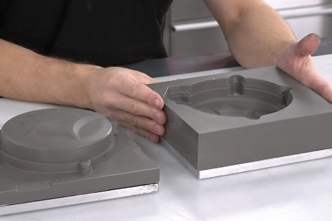

PRODUCTS USED IN THIS PROJECT
Although not necessarily an exhaustive list, the following tools and materials, supplied by Easy Composites, were used in this project.
The quantity shown below is the approximate amount used in the project rounded up to the nearest available kit size or quantity.
ANCILLARIES


VIDEO TUTORIAL
Casting a Two-Part Compression Mould for Forged Carbon
WHAT YOU WILL LEARN
In this video tutorial we demonstrate how to create two-part matched tools or compression moulds that can be used to produce forged carbon fibre components using a compression moulding process.
- What processes a 'matched tool' compression mould is suitable for
- Considerations for the mould production
- Positioning and extending the pattern using plasticine
- Casting the inside and outside mould using TC80 Tool Cast aluminium-filled epoxy casting resin
INTRODUCTION
Introduction
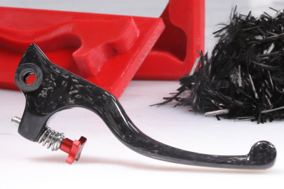
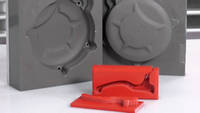
Forged carbon fibre is the term that has be adopted to describe short or ‘chopped’ strands of carbon fibre that are compression moulded in multi-part mould to create strong solid geometries that would not be practical using conventional composite processes.
Compression mould tools will comprise of 2 or more parts which close together leaving a cavity where the component will be formed, in almost all circumstances the mould will be in a ‘block’ like format to provide strength and make the clamping or compression process practical.
The main consideration when designing tooling for this process is to include a telescopic section where the male tool acts like a piston inside a cylinder during closure, this allows room to load the uncompressed fibre and then during closure and excess resin will be squeezed out through the parting line but, being very closely fitting, the fibre cannot escape leaving you with the correct fibre to resin ratio. This telescopic or ‘piston-like’ element needs to be deep enough to allow the mould to start to close before disturbing the fibre, the exact size of this feature will vary depending on the mould shape and design but a general rule of having the feature extend at least 25% of the depth of the final component would be a good estimate. In the case of a 2-piece mould this feature will require a slight draft angle of 2-3 degrees to allow the mould to easily separate, in multi-part tooling it is often possible to design the mould so that it can separate away from a completely parallel ‘piston’ feature.
WHAT YOU WILL NEED
Materials and Equipment Needed for the Compression Mould
RW4 Release Agent
RW4 high build spray release wax is the recommended release system for ambient temperature compression moulding, this release agent performs particularly well when releasing rigid mouldings and castings from one another as it provides a thick barrier that is relatively soft and so can move a little during release if needed.
Mould Release Wax
Traditional mould release wax used to release coat the original part to ensure the casting resin does not stick to it.
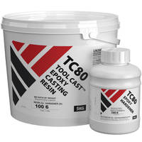
TC80 ToolCast Epoxy Casting Resin
TC80 is an epoxy casting resin designed for casting a wide array of tooling. In this particular case it is ideal for use when making small to medium sized compression tooling for use in the forged carbon fibre process
Plasticine
Plasticine is ideal for extending any pattern to give the necessary telescopic section which is essential to allow the initial compression of the two mould halves. It is firm enough to hold it shape during the resin casting yet can be easily shaped and smoothed by hand. Also it can be reused once the mould is finished.
Filleting Wax
Filleting wax and/or plasticine is often useful for sealing threads on mould bolt threads or to infill and seal ejection holes in the mould.
Polypropylene Sheet
Ideal for making mould baseboards sides and flanges. Can be easily cut to shape and glued with hot melt glue. Naturally does not stick to most resin systems meaning without release agents it can be peeled from the finished mould.
PROJECT BREAKDOWN

1. Release Coating the Original Part
The original part will need release coating to prevent the resin sticking to the part when it cures. Apply 5 coats of the mould release wax to the part taking care to ensure that the whole part is coated. Each coat is applied then gently buffed off. Allow 15 minutes between each coat.

2. Filling in any holes or unwanted detail
Use plasticine to fill in any holes or unwanted detail on the final part. The holes on the cover are easier to drill out post processing so in this case they are filled with plasticine. The demoulding wedges will easily and quickly trim the plasticine to give a neat finish to the filled hole without scratching the plastic.
3. Creating Perimeter Extension
It is essential to include a perimeter extension where the male tool acts like a piston inside a cylinder during closure. This allows room to load the uncompressed fibre and then during closure and excess resin will be squeezed out through the parting line.
First of all, a baseboard is cut from polypropylene sheet which is an ideal surface for the moulding process. A large amount of plasticine is used to create the perimeter extension around the base of the part. Remember when trimming the plasticine to allow a draught angle of 3 to 5 degrees to aid in both the compression process and also demoulding at the end.
A final coat of mould release wax is applied to ensure the surface is smooth and that there will be an easy release of the finished mould.
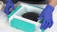
4. Making the Mould Box
Polypropylene is used as it naturally releases from the resin once cured. Cut strips of the sheet to make edges for the mould. Once aligned, the sheets are hot melt glued into place before being sealed with the hot melt glue. It is essential for the box to be fully sealed so the resin does not leak out. Blocks of wood or similar material are then bonded onto the outside of the mould box to provide additional support and strength.
5. Pouring the first half of the Compression Mould
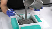
The TC80 ToolCast is ideal for this application due to its ease of use and tough nature. Measure out the correct amount of resin and hardener into a mixing cup. Thoroughly mix for 2-3 minutes taking care to scrape the sides and bottom of the cup. Pour into a clean cup and mix for a further 2-3 minutes.
Initially brush a layer of the TC80 ToolCast onto the part surface, this is to break any surface tension and ensure you do not get any resin voids or air bubbles on the mould surface. Then back fill with the rest of the resin. Allow a minimum of 24 hours at 20°C for the resin to cure before attempting to demould.

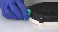
6. Demoulding and Preparing for the Second Pour
Now that the resin has fully cured we can remove the barriers and baseboard. Keep the barriers as they will be reused later. Turn over the mould and scrape out the plasticine from the underside, taking care not to remove or demould the original part. The original part must remain in the mould to create the cavity for the compression moulding process. Once most of the plasticine has been cleaned up, use a thin coating of mould release wax to remove any final residue,
Refill and redress any holes to ensure they are still sealed with the plasticine for the next pour. Also any unwanted detail can be filled in on this side with plasticine in the same way. To help with demoulding, it is wise to create wedge driving locations. Create a wedge shape using plasticine and trim and shape using a demoulding wedge. This will help demoulding as it is then possible to drive a demoulding wedge into the matched recess.
The barriers from before are then reused to create barriers for the second pour. Double sided tape is then used to bond them into place and, like before, hot melt glue is used to fully seal the barriers on the outside of the barriers to give a neater finish to the mould. Then, using filleting wax, carefully run around the inside edge of the mould box to ensure there is a seal between the barriers and the resin.
The mould then needs to be sprayed with the RW4 Spray release agent. It builds up a thick but slightly flexible layer which will help with demoulding. Typically 3 to 4 coats are used in this application. It is not used on the A side of the mould as it leaves a slight textured finish, however this is not an issue on the reverse of the part which is not seen when fitted.

7. Pouring Second Side of the Mould
Pouring the TC80 ToolCast resin is an identical process to the first side of the mould. Measure out the correct amount of resin and hardener into a mixing cup. Thoroughly mix for 2-3 minutes taking care to scrape the sides and bottom of the cup. Pour into a clean cup and mix for a further 2-3 minutes.
Initially brush a layer of the TC80 ToolCast onto the part surface, this is to break any surface tension and ensure you do not get any resin voids or air bubbles on the mould surface. Then back fill with the rest of the resin. Allow a minimum of 24 hours at 20°C for the resin to cure before attempting to demould.
8. Demoulding and Finishing the Compression Mould
Now that the TC80 ToolCast resin has fully cured, you can begin the demoulding process. The polypropylene barriers should easily be removed leaving the 2 part solid block mould. At this stage the mould is going to be reinforced before separation and demoulding.
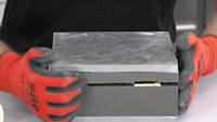
To add strength to the mould to avoid cracking when demoulding, an alloy sheet is going to be bonded to each half. The surfaces to be bonded are heavily abraded with a Perma-Grit Sanding block then cleaned. Our VM100 Black methylmethacrylate adhesive is used to bond the alloy sheets to both sides of the mould and then allowed to cure.
Once the adhesive has cured, demoulding wedges are inserted into the demoulding gaps and used to slowly separate the 2 halves of the mould. Care is taken to separate evenly on each side to avoid the two mould halves jamming against each other and the part in the middle. Once the gap has opened nicely, it should be possible to separate the 2 mould halves by hand.
Carefully prising the edges of the part to flex it away from the mould wall, carefully work the part out of the mould and then remove the part from the mould. Clean up any residue of wax and plasticine and remove any flash lines or rough edges on the mould. Thoroughly clean the mould prior to use. The two part compression mould is now ready to be used to make a forged carbon part.
DISCUSSION (13)
Please share any questions or comments you may have about this video tutorial.
Whilst it is possible to compression mould more continuous fibre formats of carbon reinforcement, like a woven cloth, you'll find woven reinforcements much more restrictive in terms of the shapes that you can successfully mould.
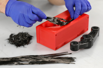
The reason this process works so well with chopped carbon fibre tow is because the individual, short strands of carbon fibre are fairly free to move around and distribute themselves in the mould under pressure. If you use a woven cloth, the fibres are continuous and bridge right across the component's surface, as you add pressure, it starts to lock the reinforcement in place and doesn't allow it to redistribute into corners, cavities, details etc. The result, if you made a part like this flywheel cover, is voiding/bridging in various areas of the component. However, for parts that are predominantly flat or with only gentle contours, you might get away with a woven reinforcement. One option might be a hybrid approach where you use woven cloth on the surface and then back it up with chopped tow, effectively getting the best of both worlds. Again, it would depend on the geometry of the part you're making.
This telescopic or 'piston-like' element needs to be deep enough to allow the mould to start to close before disturbing the fibre. The exact size of this feature will vary depending on the mould shape and design but a general rule of having the feature extend at least 25% of the depth of the final component would be a good estimate. In the case of a 2-piece mould this feature will require a slight draft angle of 2-3 degrees to allow the mould to easily separate, in multi-part tooling it is often possible to design the mould so that it can separate away from a completely parallel 'piston' feature.
There's a couple of things to consider in terms of the suitability of a prepreg for a compression moulding process. Firstly, we must consider the resin system itself. In order for a prepreg resin system to be suitable for us with a two-part compression mould made using the TC80 Tool Cast resin, you must ensure that the resin system can be cured at a temperature within the service temperature of the TC80, which is 80°C. Although the recommended cure temperature for our XPREG component prepregs, XC110 and XC130 is 120°C, they could both be *initially* cured down at 80°C (cure time will be longer of course) and then de-moulded (from the TC80 tool) before being 'post-cured' at a higher temperature in order to improve their Tg and mechanical properties.
With regard to the reinforcement itself, conventional reinforcement formats such as woven fabric, multiaxial and unidirectional, are not well suited to compression moulding. The reason is because the reinforcement needs to be able to 'move around' inside the mould, allowing it to reach areas of the mould where there is less reinforcement, fill cavities, and match the thickness of the gap between the compression tools. All of these things are difficult for a continuous fibre format to achieve. Instead, what's required is a short strand reinforcement, like chopped tow or chopped UD prepreg. At the moment, such prepregs are very rare and we don't currently have one within the XPREG range, however, we are working on one and hope to add it to our range very soon.
Yes, indeed. In the accompanying video (which we'll be releasing next week hopefully) we use 3D printed moulds, alongside this solid cast one, to produce the forged carbon parts. Resin printing is potentially good for producing solid 3D prints but does often compromise the dimensional accuracy, certainly in our experience anyway, but yes, they do yield a better surface finish.
Thanks mainly to Lamborghini, over the last few years, the phrase 'forged' carbon has come to mean composite components made using short strand, randomly oriented carbon fibre, moulded under pressure. It differs from components laminated using more traditional formats of carbon fibre (i.e. woven carbon fibre cloth) in that the shorter strands of carbon can move around in the laminate, allowing them to fill more complex mould shapes under pressure in a way that woven or long-strand unidirectional fibre won't do. The compromise though is ultimate strength - components made with long strand unidirectional or woven reinforcement will be stronger and can exploit optimised fibre orientation (i.e. fibres aligned in the direction where strength is most needed) to produce components with better mechanical properties. In short, forged carbon compromises on strength but provides a material that can 'flow' better in compression moulding, meaning it can be used in a way that woven or UD materials cannot.
Good question. We're engineers too and they matter to us as well so we did have several conversations about this internally before making the video! I'll try to provide a detailed reply of where we got to on our thinking:
First of all, this isn't our name for the process, it's a fairly well-established way to describe compression moulded short strand carbon fibre - mainly because Lamborghini have been calling it 'forged carbon' and using it extensively for a few years now. Calling it anything else would require active effort (and mean a lot of people interested in 'forged carbon' don't find our information).
Secondly, on the etymology of the word 'forged', both in an established engineering context, and in its suitability and applicability in a composites context (regardless of whether Lamborghini and others were using it) we don't think it's far from the mark. Whilst 'forged' means something specific in a context of forming metal, the word forged also means "formed by pressing or hammering with or without heat" (Merriam Webster dictionary) or "to make or produce something, especially with some difficulty" (Cambridge dictionary). Given that the process - in this context - refers to compression moulding under pressure, this description does seems pretty apt.
Whilst you could certainly call a 'forged' carbon fibre part 'compression moulded carbon', you could actually call most carbon fibre parts 'compression moulded' because many processes - vacuum bagging, prepreg, SMC etc, are all forms of compression moulding. Forged carbon is a way of differentiating compression moulding short strand carbon from traditional woven or long strand reinforcement. The short strands being key to the process in allowing the reinforcement to 'flow' more easily to conform to the mould contours under pressure in a rigid tool, something that doesn't happen with woven or long strand reinforcement (leading to voiding).
Although it bypasses vacuum bagging itself, there is still a reasonable amount of force applied in the compression stage which replicates some of the forces involved in vacuum bagging. That helps with fibre consolidation and removing excess resin.
Hi Tom, yes, you can definitely use RW4 is situations where you might also consider PVA release agent; they're similar in that they are both extremely reliable but do slightly compromise the surface finish. In most situations, a spray wax like RW4 will be even more reliable than PVA because it's applied by spray, it doesn't run the risk of fish-eying and missing areas.
LEAVE A COMMENT OR QUESTION
PRODUCTS USED IN THIS PROJECT
Although not necessarily an exhaustive list, the following tools and materials, supplied by Easy Composites, were used in this project.
The quantity shown below is the approximate amount used in the project rounded up to the nearest available kit size or quantity.
ANCILLARIES
DISCUSSION (13)
Please share any questions or comments you may have about this video tutorial.
Whilst it is possible to compression mould more continuous fibre formats of carbon reinforcement, like a woven cloth, you'll find woven reinforcements much more restrictive in terms of the shapes that you can successfully mould.
The reason this process works so well with chopped carbon fibre tow is because the individual, short strands of carbon fibre are fairly free to move around and distribute themselves in the mould under pressure. If you use a woven cloth, the fibres are continuous and bridge right across the component's surface, as you add pressure, it starts to lock the reinforcement in place and doesn't allow it to redistribute into corners, cavities, details etc. The result, if you made a part like this flywheel cover, is voiding/bridging in various areas of the component. However, for parts that are predominantly flat or with only gentle contours, you might get away with a woven reinforcement. One option might be a hybrid approach where you use woven cloth on the surface and then back it up with chopped tow, effectively getting the best of both worlds. Again, it would depend on the geometry of the part you're making.
This telescopic or 'piston-like' element needs to be deep enough to allow the mould to start to close before disturbing the fibre. The exact size of this feature will vary depending on the mould shape and design but a general rule of having the feature extend at least 25% of the depth of the final component would be a good estimate. In the case of a 2-piece mould this feature will require a slight draft angle of 2-3 degrees to allow the mould to easily separate, in multi-part tooling it is often possible to design the mould so that it can separate away from a completely parallel 'piston' feature.
There's a couple of things to consider in terms of the suitability of a prepreg for a compression moulding process. Firstly, we must consider the resin system itself. In order for a prepreg resin system to be suitable for us with a two-part compression mould made using the TC80 Tool Cast resin, you must ensure that the resin system can be cured at a temperature within the service temperature of the TC80, which is 80°C. Although the recommended cure temperature for our XPREG component prepregs, XC110 and XC130 is 120°C, they could both be *initially* cured down at 80°C (cure time will be longer of course) and then de-moulded (from the TC80 tool) before being 'post-cured' at a higher temperature in order to improve their Tg and mechanical properties.
With regard to the reinforcement itself, conventional reinforcement formats such as woven fabric, multiaxial and unidirectional, are not well suited to compression moulding. The reason is because the reinforcement needs to be able to 'move around' inside the mould, allowing it to reach areas of the mould where there is less reinforcement, fill cavities, and match the thickness of the gap between the compression tools. All of these things are difficult for a continuous fibre format to achieve. Instead, what's required is a short strand reinforcement, like chopped tow or chopped UD prepreg. At the moment, such prepregs are very rare and we don't currently have one within the XPREG range, however, we are working on one and hope to add it to our range very soon.
Yes, indeed. In the accompanying video (which we'll be releasing next week hopefully) we use 3D printed moulds, alongside this solid cast one, to produce the forged carbon parts. Resin printing is potentially good for producing solid 3D prints but does often compromise the dimensional accuracy, certainly in our experience anyway, but yes, they do yield a better surface finish.
Thanks mainly to Lamborghini, over the last few years, the phrase 'forged' carbon has come to mean composite components made using short strand, randomly oriented carbon fibre, moulded under pressure. It differs from components laminated using more traditional formats of carbon fibre (i.e. woven carbon fibre cloth) in that the shorter strands of carbon can move around in the laminate, allowing them to fill more complex mould shapes under pressure in a way that woven or long-strand unidirectional fibre won't do. The compromise though is ultimate strength - components made with long strand unidirectional or woven reinforcement will be stronger and can exploit optimised fibre orientation (i.e. fibres aligned in the direction where strength is most needed) to produce components with better mechanical properties. In short, forged carbon compromises on strength but provides a material that can 'flow' better in compression moulding, meaning it can be used in a way that woven or UD materials cannot.
Good question. We're engineers too and they matter to us as well so we did have several conversations about this internally before making the video! I'll try to provide a detailed reply of where we got to on our thinking:
First of all, this isn't our name for the process, it's a fairly well-established way to describe compression moulded short strand carbon fibre - mainly because Lamborghini have been calling it 'forged carbon' and using it extensively for a few years now. Calling it anything else would require active effort (and mean a lot of people interested in 'forged carbon' don't find our information).
Secondly, on the etymology of the word 'forged', both in an established engineering context, and in its suitability and applicability in a composites context (regardless of whether Lamborghini and others were using it) we don't think it's far from the mark. Whilst 'forged' means something specific in a context of forming metal, the word forged also means "formed by pressing or hammering with or without heat" (Merriam Webster dictionary) or "to make or produce something, especially with some difficulty" (Cambridge dictionary). Given that the process - in this context - refers to compression moulding under pressure, this description does seems pretty apt.
Whilst you could certainly call a 'forged' carbon fibre part 'compression moulded carbon', you could actually call most carbon fibre parts 'compression moulded' because many processes - vacuum bagging, prepreg, SMC etc, are all forms of compression moulding. Forged carbon is a way of differentiating compression moulding short strand carbon from traditional woven or long strand reinforcement. The short strands being key to the process in allowing the reinforcement to 'flow' more easily to conform to the mould contours under pressure in a rigid tool, something that doesn't happen with woven or long strand reinforcement (leading to voiding).
Although it bypasses vacuum bagging itself, there is still a reasonable amount of force applied in the compression stage which replicates some of the forces involved in vacuum bagging. That helps with fibre consolidation and removing excess resin.
Hi Tom, yes, you can definitely use RW4 is situations where you might also consider PVA release agent; they're similar in that they are both extremely reliable but do slightly compromise the surface finish. In most situations, a spray wax like RW4 will be even more reliable than PVA because it's applied by spray, it doesn't run the risk of fish-eying and missing areas.
LEAVE A COMMENT OR QUESTION
100% SECURE
PAYMENT METHODS
Easy Composites EU B.V., registered in the Netherlands 73601195. All content copyright (C) Easy Composites Ltd, 2025. All rights reserved.