Need any help or advice?![]() +44 (0)1782 454499
+44 (0)1782 454499
VIDEOS IN THIS SERIES
This video is part 2 of a 2 part series: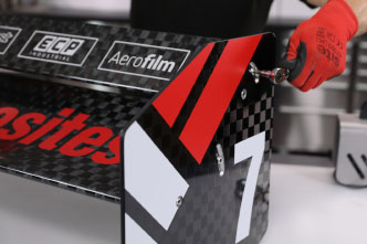
PRODUCTS USED IN THIS PROJECT
Although not necessarily an exhaustive list, the following tools and materials, supplied by Easy Composites, were used in this project.
The quantity shown below is the approximate amount used in the project rounded up to the nearest available kit size or quantity.
MATERIALS & CONSUMABLES


ANCILLARIES

TOOLS & EQUIPMENT


VACUUM BAGGING CONSUMABLES
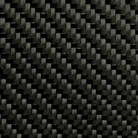
REINFORCEMENTS
VIDEO TUTORIAL
Motorsport Rear Wing Destruction Test
In this video, the motorsport wing produced in our video on Motorsport Aero Wing Construction video is load tested to destruction. If you have not seen this video yet, we would recommend watching it as it may help you work out how the wing may fail.
Why might it be advantageous to test a wing like this to destruction?
The first reason for wanting to test a wing like this is to ensure it is strong enough to withstand the down force and loads it may experience during use. Also watching and learning from destructive testing like this helps understanding of failure methods which can be important as it can influence future design based on the failure method discovered in the tests.
What is the method and test rig used?
The test rig we have designed is a relatively simple steel frame structure for rigidity, with uprights for mounting the wing in place directly into the inserts on the end. Other equipment include a dial gauge to measure the deflection of the wing during the test and a pressure gauge to measure the pressure in the inflatable bladder.
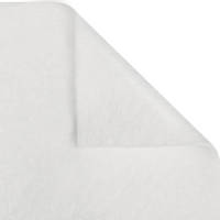
The inflatable bladder is made from Tubular Bagging Film with the ends heat sealed and a valve inserted for inflation. The heat sealer is effective at sealing the ends of the tubular film. The bag is deliberately cut oversize so that the ends can be folded over thus reducing the amount of force on the bag seals.
The valve used is a Schrader valve for a tubeless bicycle rim with the core removed. When fitted it seals on the bag through a counter sunk hole drilled in the rig and once tightened up, a hose can be attached for inflation.
The wing can then be installed by bolting it to the uprights. Rubber washers are used to allow a degree of flex during the test as the wing deflects.
The gauge is then plumbed in and connected to a pressure source and the dial indicator gauge located using a simple magnetic base for support.
Normally for such tests, the bladder would be inflated hydraulically with water. This is because water is incompressible and as such when the wing does get to the point of failure, the fluid contains much less stored energy meaning the failure is likely to be much more controlled and contained from a safety perspective. However, for this test, to achieve a more interesting and potentially dramatic failure, we are pressurising it with air. It is not recommended to do this and we are working with safety precautions to minimise any risk from using air.
Results
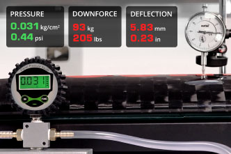
In the first test, the maximum deflection of the wing is measured for the intended amount of downforce this wing will produce. In this case, that is 100kg of load which produced a deflection of 6mm. This is perfectly acceptable for wing of this type and intended application.
At this point, the dial indicator is removed and the pressure increased to determine the ultimate failure point and method. This kind of test does have some compromises, namely we are only applying force to one side of the wing and also, due to tension in the film, there will be some uneven pressure and force applied by the bladder. Despite these compromises in the test method, it will still produce data that is useful for the application.
The first point of failure, the insert is ripped clean out of the wing. However this was well above any expected load on track. This failure method was partially as a result of the design of the test rig being so stiff - the fixings in the end of the wing were thus under a large amount of pulling force as the wing deflected until the point the insert was ripped out. The damage was limited to some delamination and the ripped out insert and it would be perfectly possible to repair and put back into use.
To really see how much load the main element can take, a further test is carried out. To support the wing properly during the test, saddles are fabricated to have an even contact area on the wing surface to help evenly distribute the load. The bladder is then inflated for the second time until the point of failure.
The wing eventually does fail in a dramatic and catastrophic way as seen in the video! As might be expected, it fails almost exactly in the middle of the wing where the peak stress likely to be. The side in compression has failed first with a full fracture which as propagated to the side under tension. The trailing edge has partially delaminated due to inter-laminar shear.
There is no argument that the wing has suffered a catastrophic failure but this occurred at a load of 1200kg which is massively in excess of anything this wing would experience in use!
Conclusion
In conclusion, it can be clearly seen from the tests that this wing can withstand much higher loads than would ever be experienced on the race track. Secondly, at its intended design level of downforce - 100kg - the wing had a deflection of 6mm which is more than acceptable.
The fact that the wing could withstand over 8 times its designed level of downforce does indicate the wing is stronger than it needs to be. This means the design of the wing could be further optimised to maximise its stiffness and reduce strength by reducing the overall amount of material used in the wing and hence reducing its weight.
DISCUSSION (6)
Please share any questions or comments you may have about this video tutorial.
For this video we used am imported FS600H model which is rated to 0.8kW power. Other similarly powered Heat sealing machines should also work fine.
Thanks for the question. The 100kg downforce was calculated by a team who we worked with on this wing. Unfortunately we cannot make their data public but there are a number of ways that the loading can be established, from CFD software through to physical wind tunnel or track testing.
We did make it with FSAE students partially in mind as well as other club and entry levels of motorsport.
..... don't forget a real-world race car wing is used as a tool table by mechanics and a push bar by the pit crew and after the racing is over, it's used as a table on which to mix drinks and serve snacks. And if your driver wins, he might just use the wing to climb on top of the car so that he/she can soak up the adoration of the fans. You don't want someone crippling a thin skin by dropping a ratchet wrench or a cold beer on your wing.
Ultimately depends on the specific race series and the way the team is managed. But certainly you could factor in additional strength if that was needed for non-aero reasons.
Within the limiting factors of the aerofoil design and blade angle of attack, yes. Fitment is very much down to the style of race car design and also, sometimes, racing class restrictions. The design can also be modified to suit the specific planned mounting arrangements.
..... You said the first side to fail was the one in compression. I'd take from that, that there is enough carbon to take up the tensile forces. Now, i always imagine epoxy and carbon to be like concrete and rebar, one component for tension and one for compression. Would adding more epoxy to the wing increase the compressive strength of it, until with enough of it, the side of the wing under tension would fail first? This would obviously add quite a bit of weight, but i'd think it would be less weight than another layer of carbon, since epoxy is less dense, it would also be cheaper than a whole new layer
A more resin rich laminate would not be stronger in that sense. Additional layers of laminate would be the best way to increase the strength of the wing if you needed it. You could go further and use additional methods mentioned in the first video, such as use of spars, uni-directional fibres etc, which means you can make the wing stronger and use the laminate in a more efficient way to keep the weight down.
LEAVE A COMMENT OR QUESTION
PRODUCTS USED IN THIS PROJECT
Although not necessarily an exhaustive list, the following tools and materials, supplied by Easy Composites, were used in this project.
The quantity shown below is the approximate amount used in the project rounded up to the nearest available kit size or quantity.
MATERIALS & CONSUMABLES
ANCILLARIES
TOOLS & EQUIPMENT
VACUUM BAGGING CONSUMABLES
REINFORCEMENTS
DISCUSSION (6)
Please share any questions or comments you may have about this video tutorial.
For this video we used am imported FS600H model which is rated to 0.8kW power. Other similarly powered Heat sealing machines should also work fine.
Thanks for the question. The 100kg downforce was calculated by a team who we worked with on this wing. Unfortunately we cannot make their data public but there are a number of ways that the loading can be established, from CFD software through to physical wind tunnel or track testing.
We did make it with FSAE students partially in mind as well as other club and entry levels of motorsport.
..... don't forget a real-world race car wing is used as a tool table by mechanics and a push bar by the pit crew and after the racing is over, it's used as a table on which to mix drinks and serve snacks. And if your driver wins, he might just use the wing to climb on top of the car so that he/she can soak up the adoration of the fans. You don't want someone crippling a thin skin by dropping a ratchet wrench or a cold beer on your wing.
Ultimately depends on the specific race series and the way the team is managed. But certainly you could factor in additional strength if that was needed for non-aero reasons.
Within the limiting factors of the aerofoil design and blade angle of attack, yes. Fitment is very much down to the style of race car design and also, sometimes, racing class restrictions. The design can also be modified to suit the specific planned mounting arrangements.
..... You said the first side to fail was the one in compression. I'd take from that, that there is enough carbon to take up the tensile forces. Now, i always imagine epoxy and carbon to be like concrete and rebar, one component for tension and one for compression. Would adding more epoxy to the wing increase the compressive strength of it, until with enough of it, the side of the wing under tension would fail first? This would obviously add quite a bit of weight, but i'd think it would be less weight than another layer of carbon, since epoxy is less dense, it would also be cheaper than a whole new layer
A more resin rich laminate would not be stronger in that sense. Additional layers of laminate would be the best way to increase the strength of the wing if you needed it. You could go further and use additional methods mentioned in the first video, such as use of spars, uni-directional fibres etc, which means you can make the wing stronger and use the laminate in a more efficient way to keep the weight down.
LEAVE A COMMENT OR QUESTION
100% SECURE
PAYMENT METHODS
Easy Composites EU B.V., registered in the Netherlands 73601195. All content copyright (C) Easy Composites Ltd, 2025. All rights reserved.