Need any help or advice?![]() +44 (0)1782 454499
+44 (0)1782 454499
VIDEOS IN THIS SERIES
This video is part 1 of a 2 part series: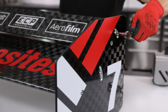
PRODUCTS USED IN THIS PROJECT
Although not necessarily an exhaustive list, the following tools and materials, supplied by Easy Composites, were used in this project.
The quantity shown below is the approximate amount used in the project rounded up to the nearest available kit size or quantity.
MATERIALS & CONSUMABLES
TOOLS & EQUIPMENT

VACUUM BAGGING CONSUMABLES
ANCILLARIES
REINFORCEMENTS
VIDEO TUTORIAL
Mouldless Motorsport Wing Construction
In this tutorial video, we are covering a mouldless method of creating an aero rear wing assembly ideal for mid to low level motorsport applications. This uses an XPS Polystyrene core and Mylar film to create the smooth surface. Making structural end plates and inserts is also covered.
INTRODUCTION
Downforce producing wings are an essential part of many motorsport vehicles. This video will demonstrate how to make an effective aero rear wing using a simple mould-less construction method.
High end motorsport such as F1 and mass produced wings will generally still use a moulded construction method so this mould-less technique is ideal for Club level motorsport, Time Attack, Formula Student and other similar motorsport disciplines where a light but strong method of making a one off or low volume wing is preferred.
Although the foam core and inserts made during this video were cut using CNC machines, they could be cut without CNC equipment easily enough helping this method of wing construction remain accessible.
WHAT YOU WILL LEARN
The following key areas are covered by this video tutorial:
- How to Profile the Wing Core using a Hot wire Cutter.
- Creating Suitable Hard points and Inserts.
- How to Laminate and Vacuum Bag the Carbon fibre onto the Core using Mylar.
- How to Produce Light Weight End Plates using Nomex Honeycomb.
WHAT YOU WILL NEED
Materials and Equipment Needed to Complete the Project
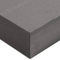
XPS Polystyrene Foam - To be cut to shape for the wing core. Chosen for its smooth finish, light weight and ability to be cut by hot wire.
Hot Wire Cutter - To cut the wing profiles to the desired shape. This can be done using a simple hand bow wire cutter or a more advanced multi-axis CNC hot wire cutter.
Aluminium sheet or section - For fabricating inserts and hard points. Aluminium is used for its good all round strength, ease of machining and relative lightweight compared to other metals.
Masking Tape - Helps bind edge of Spread Tow fabric to prevent it falling apart.
88g Spread Tow Carbon Fibre Fabric - Produces a smooth and high quality cosmetic finish as the surface layer fabric on the wing.
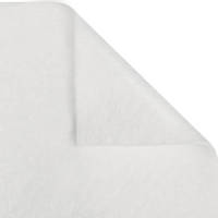
Paper Roll - To separate the first layer of reinforcement as it is rolled up ready for use.
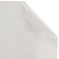
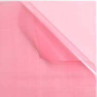
Mylar Release Film - This film is key to giving the smooth surface to the wing and with its thickness, flexible properties and easy release makes it ideal to wrap around the wing during production.
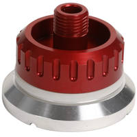
Vacuum Pressure Regulator - Reduces vacuum level to the 20% vacuum needed when producing the wing end plates.
Spread Tow High Strength Sheet - Easy to use and cut stock sheet to make the skins for end plates.
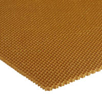
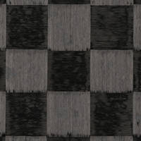
Nomex Honeycomb 5mm - Light weight and strong Structural Core for making the end plates.
STEP-BY-STEP GUIDE
1. How to Profile the Wing Using a Hot Wire Cutter
The core material being used for this wing is XPS or extruded polystyrene which has a smooth finish when cut rather than the beaded polystyrene. It also has better mechanical performance.
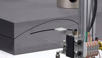
Although the XPS could be hand cut, the level of accuracy is pretty low. The most efficient way is to use a hand bow hot wire cutter and will give good accurate wing profiles. In this case, we are using a 4 Axis CNC hot wire cutter that we already had available. Although for these profiles we are only using the 2 axis function.
An important point with any hot wire cutter is not to cut too fast. If cut too fast, the wire will drag and this can distort the cut profile. The speed should be set such that the foam melts just in front of the wire with the wire not touching the foam. As a rough guide, these profiles were cut at a speed of 200mm per minute. Once cut, the profiles can be extracted from the foam block ready to make the wing.
2. Creating and fitting the Hardpoints and Inserts
To mount the wing, it is essential to have inserts or hard points for the fixings as the composite and foam would not take the loads adequately. To make these, 8mm aluminium sheet has been CNC machined to shape, although it could be cut with most common machine tools if CNC was not available and even made in MDF for simple applications.
The cut inserts are sanded then cleaned with acetone to degrease prior to being bonded to the foam cure using the Permabond ET500 Adhesive. This is used to bond the foam sections together. Care needs to be taken to avoid any gaps or ridges as these can print onto the wing surface. At this stage any gaps can easily be filled with the adhesive.
3. Preparing Materials for the Wing Construction
Mylar film is going to be key to this process. It is non-stick and in the 125 micron thickness used here, has the correct balance of flexibility and surface finish for the wing application. The Mylar needs to be accurately measured to length against the core. The reason will become clearer as the wing is manufactured. In the other direction, the Mylar is cut 50mm oversize to give an overlap on the trailing edge.
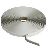
An envelope vacuum bag will be used to consolidate and compress the wing while it cures. It should be prepared in advance at this stage leaving one side open ready to insert the wing. The other sides can be sealed with gum tape and the through bag connector pre-installed.
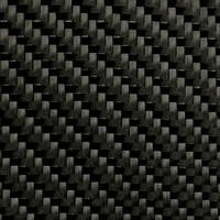
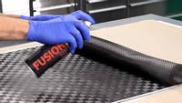
The reinforcement is now prepared by cutting it to shape ready for use. The surface cosmetic ply is our 88g Spread Tow Carbon fibre which has both a very flat finish and a stunning cosmetic appeal. However, Spread Tow fabrics are very fragile once cut, easily fraying when handled. To prevent this issue, masking tape is applied on all the cut lines to help hold it together. The fabric is oversized by approximately 20mm in both directions. The rest of the reinforcement is made up of 3 plies of the 210g twill woven carbon fibre cloth.
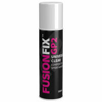
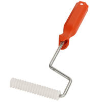
To help stabilise the Spread Tow fibre even further, the fabric is sprayed with Fusion Fix Spray Tack Adhesive and one ply of the backing fabric is carefully rolled over the Spread Tow to stabilise it. A plastic finned roller is used to ensure the two layers are well consolidated together. The fabric can then be rolled up with a paper separator ready for use.
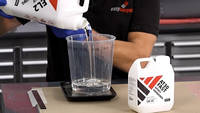
4. Measuring and Mixing the Resin
For this project, the ideal resin is the EL2 Epoxy Laminating Resin. It has the right balance of medium viscosity and good mechanical performance for this process. To work out the correct amount of resin, first weigh the total amount of fabric reinforcement that has been precut.
Due to the resin needed on the Mylar film and the fact excess resin is squeezed out, more resin is used than would be typical for a wet lay process. Take the figure measured above and double it so twice the amount of resin as the weight of the fibre is used.
As with all composites, it is important to carefully weigh out the resin according to the mixing ratio on the bottles then thoroughly mix before use. It is recommended to mix for several minutes in one bucket, before pouring into a second clean bucket and mixing again.
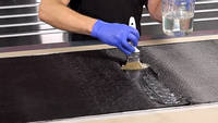
5. Applying the Resin and Laminating the Reinforcement
At this stage approximately one third of the resin is poured onto the Mylar film and spread out into an even layer. The first layer of reinforcement is then carefully laid out onto the resin and the plastic finned roller used over the surface. Working back and forth with the plastic finned roller in this way will help the resin wet out the fibres and work its way through the reinforcement. This tends to result in a better consolidated material and less trapped air than working from behind.
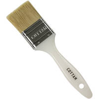
Once the surface has been fully rolled over, more resin can be applied and the process repeated for the remaining layers of reinforcement. It is important that the resin layer is spread out evenly all over the surface. The final layer should, once fully rolled over should look quite wet. This excess resin will help applying the core to the reinforcement allowing it, and the Mylar, to slide and move as necessary. Although rollers are ideally suited to this process, spreaders or a brush used carefully can create the same effect.
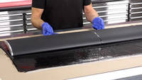
6. Placing the Core and Wrapping in Mylar
Now the reinforcement has been fully wetted out, the core can be carefully placed on the reinforcement. The Mylar film is then wrapped around the core and the position of the core can be adjusted to get the position nice and central. It is normal for the Mylar and fabric to seem quite loose against the core at this stage. The Mylar is then wiped down to remove any excess resin and the wing placed into the vacuum bag.
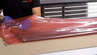
7. Vacuum Bagging the Wing
The wing is now carefully placed into the premade vacuum bag. The wing should be positioned so the leading edge is pressed against the fold in the bagging film. The film can then be tightened and smoothed other the wing surface to remove any excess film and creases.
A strip of heavy weight breather is then placed over the trailing edge of the wing and the gum tape can now be sealed. Vacuum can now be pulled on the bag.
It is important to gradually pull the vacuum slowly and regularly stop to remove creases from the Mylar film and remove excess resin by carefully squeegeeing the surfaces of the wing. An ideal tool to act as the squeegee is a piece of the foam with some breather cloth over the edge.
Once the excess resin has been removed and the Mylar is sitting flat and crease/wrinkle free, full vacuum can be applied and the bag left to cure. It should be laid out so that the trailing edge flows straight out from the profile.
The second element is produced in exactly the same way as the first. This layup has been optimised for simplicity and could be improved in many ways. The first method would be the inclusion of spars in the core of the wing. This means the skin can be thinner and thus reducing the weight. A simple method is to cut the foam vertically and bond in a premade piece of carbon sheet. It can be further improved with the use of end caps and ribs.
Further improvements can be made in the layup itself. A simple 0 and 90 degree layup is not the most efficient and could be improved with more careful laminate orientation and layup.
8. Preparing the End Plate Materials
As the end plates are taking the load from the wing into the chassis, they need to be constructed in a very strong way. Ideally for such applications, a sandwich panel construction method is ideal. In this example, 2 layers of a 1mm Spread Tow carbon fibre sheet will be sandwiched either side of a 5mm Nomex Honeycomb core material.
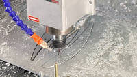
The Carbon sheet is cut to shape using our CNC router, although this could be done by hand if this was not available. The carbon cuts very cleanly with no further finishing required. A 1.6mm carbide burr is the cutting tool used as they quickly and easily cut the carbon sheet. Full dust extraction should be used to reduce and minimise the hazard from airbourne dust.
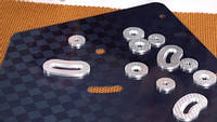
At this stage the inserts will need to be made. Wherever there are fasteners passing through the end plate, there are high compressive loads which may crush and damage the core, The inserts, usually made of aluminium, will spread the load and prevent this crushing from happening. These inserts have been machined from aluminium and cut by CNC. For simple applications these could even be made from MDF.
The bonding surface of the inserts is keyed with sand paper and the inserts are cleaned and degreased. They can then be bonded into place on the carbon sheet using the VM100 Black Adhesive. The peel ply texture on the reverse of the carbon sheet is ideal for bonding to and thus needs no further preparation.
When bonding aluminium directly to carbon fibre, it is important to consider if galvanic corrosion is likely to be an issue for the specific application. In this case, it is a dry stored race car and thus is not an issue so no action is needed to be taken. However for some other applications such as marine or aviation, it is important to isolate the aluminium from the carbon. This is easiest done by laminating a thin layer of glass fibre between them.
The Nomex Honeycomb can now be carefully cut to shape using a scalpel. The edge of the Nomex is cut slightly short of the end plate edge to allow a small gap that can be filled for sealing the panel edge. Cutting around the inserts is also an easy task with the ability to slightly deform the honeycomb sideways to get a tight fit against the inserts.
9. Bonding Together the End Plates
At this stage, the end plate components are ready to be bonded together to make the final finished part. To do this, the ER1 Epoxy Rapid Repair resin is used as an adhesive. This is because of its great mechanical performance and relatively quick cure time. To make it suitable for use, it is necessary to thicken the resin system to an adhesive consistency using Fumed Silica Thixotropic powder.
The resin is measured out as normal and then the fumed silica is gradually added to the resin to thicken it. The aim is to thicken it to the consistency of a typical gel coat. Once this has been achieved, the hardener can be added and the resin thoroughly mixed before use.
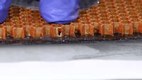
The resin is then spread evenly onto both the carbon sheets at a quantity of approximately 500g per square meter. A notched spreader will work well for this or even a brush on smaller pieces like this. The Nomex Honeycomb is then positioned on the carbon and is slid sideways in both directions. This is to enable the resin to form a fillet on the honeycomb paper sidewalls to increase the bonding surface area considerably.
At this stage the end plates are vacuum bagged to help apply an even level of force on the panel. An MDF spreader is used to ensure the edges of the panel do not distort where there is a gap in the honeycomb. It is important in this case to only use a partial vacuum through a vacuum regulator. If full vacuum was used, it can cause problems with all the resin being forced out from the edge of the panels and the problem of the adhesive excessively bubbling or foaming as the air makes its way out. For this reason, only about 20% vacuum is needed. The use of a vacuum regulator allows this to easily be set up at the ideal level. The end plates can then be left to cure under vacuum for 6 hours before removing from the bag.
10. Sealing the edges of the End Plates
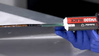
Now that the endplates have cured, they can be removed from the bags. To seal the edge, squeeze VM100 Black adhesive into the edge. It has the rapid cure time, high viscosity and ease of sanding which makes it ideal for this application.
once the edge has been filled, it can be evened off using a flat edge of a spreader then allowed to cure. Once cured, the edges can be sanded smooth to finish them off. Bringing the sanding up to 800 grit will leave a nice even and neat finish to the edge.
11. Final Wing Finishing and Assembly
At this stage, the wing elements should be fully cured and can be demoulded from the vacuum bag. The release properties of the Mylar show through here as it easily peels off the wing surface and exposes the smooth glossy finish to the wing.
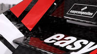
The edges and ends of the wing can now be tidied up ready for assembly and any holes tapped to add a thread. The Blue film can be removed from the end plates and any stickers and decals applied. The wing elements are then simply screwed together to give the finished duel element wing.
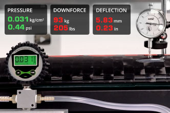
Now you can see the finished wing and the quality shines through. The use of a light foam core and carbon fibre means the total weight for this wing is only 3.5kg and it is more than strong enough for the amount of downforce it can produce. We have produced a video showing just how strong this wing is through destructive testing!
The end plates have a high level production quality to them and the VM100 especially leaves a nice edge. The Mylar leaves a very high gloss finish to the wing elements. The main compromise of this method of wing construction is surface flatness that can be achieved with the Mylar film. There is always likely to be an element of rippling to the wing surface, although this is not going to have any impact on the wings actual performance. Also such a method will lead to a slightly heavier wing due to the higher resin quantity used. However, on balance it is still a very good method for producing a one off or low volume wing.
DISCUSSION (25)
Please share any questions or comments you may have about this video tutorial.
The same method should work as long as your core is strong enough, eg experiment with printed infill etc. For a complex shape, you will almost certainly have issues with creases if using a single piece of mylar as it does not easily stretch or conform over complex curves. You may need to cut and overlap to remove creases/folds and expect a little bit of refinishing being necessary.
That is useful to know it worked well for your application with thicker Mylar. The reinforcement shown in the video was a simple lay up which worked well, but could be refined further as mentioned so the extra strip of reinforcement around the leading edge is a good way to optimise the lay up for the glider.
You are, of course, 100% correct. We do mention this as a shortcoming of this method (as well as surface rippling), however the simplicity of this method and ease for one off applications means its advantages far outweigh the weight penalty for many people. Many FSAE and similar teams are on tight budgets, tight development times and hence sometimes the compromise in weight is worth it.
If you look closely you will see the breather over the trailing edge and also under the Through Bag Connector. That is enough of an air path to allow trapped air to work its way out the laminate.
That is very chassis specific hence why we have not covered it here.
In theory you could wrap carbon fibre around most core materials, however its not necessarily going to be the most efficient way of making the part but if your shape dictates using that material then it should work.
It depends whether the wing design is parallel (or features more complex compound shapes), and also whether the mould design gives you access into the ends (i.e. the moulds are open ended). If it's parallel and open ended then you can lay up the top and bottom, then bring them together 'wet' and carefully add additional wet reinforcement over the join. If you don't have access via the ends then usually you'd need to make the two halves separately and then bond them together afterwards.
The tape is not removed. As the fabric has been very slightly oversized, the edges with the tape are trimmed off at the end of the wings production.
There's no 'wrinkles' because the Mylar isn't folded or creased but there are ripples/wobble, which we cover honestly in the roundup, including panning the camera along the wing to show the ripples.
Gliders are a good subject to demonstrate a lot of interesting and important concepts, much like any aircraft wing. On the hotwire, the whole profile is cut in one go, accuracy of the top and bottom should both be very good (more than enough for this process); we see less than 0.5mm tolerance.
It was drawn up as a generic wing rather than anything specific. However the specific profiles used were 'Eppler423' for the main element and 'NACA4412' for the Secondary element.
If you're talking about the ripples/wobble in the surface then this is more to do with the reinforcement that's added to the outside (and the varying amounts of resin) rather than inconsistency/irregularity of the core so I don't think that the ripple would could be improved by a 3D printed core and it would be difficult to print a core anywhere near as low density as the XPS (which is about 25kg/m3 or (aka a density of 0.025).
Hi Keith, yes, it does provide a much better starting point in terms of surface finish. It's by no means perfect, as we discussed in the video, but for a lot of applications it's more than good enough and means very little work on the surface.
Hi Rolf, we wondered exactly this thing. So we tried it! And…. it didn't really work! The slight variation in thickness of reinforcement caused too many areas which didn't get enough consolidation pressure. There may be some changes to the process which would improve things but from what we found, the foam 'off cut' wasn't what we hoped it might be!
Hi Matt, vote noted! We want to do it too. Got the next few lined up already but stay subbed and hopefully we'll get to it soon!
No, even at full vacuum the XPS is fine. Expanded polystyrene wouldn't take it but we certainly wouldn't recommend EPS anyway.
Thanks for the comment, I prefer to cut the top first as otherwise the weights on the foam sag the entire block, meaning that the top surface would end up offset slightly, I've never had a problem with where the wire exits, but I'm sure there might be times when cutting bottom first would be preferable.
They’re similar in terms of compressive strength per gram and so the difference (and preference) is more nuanced. For these end plates, the sheer force is quite limited and so the lowest density core would be the best option. Since it’s hard to match the low density of a nomex core in aluminium, the preference here is nomex.
We had a couple of practice runs at the smaller element, just to hone the process, but that was about it. It’s hard to say how much time from start to finish but, excluding building the hotwire, we’d finished filming in 3 days, and most of that time was things curing so, given the size and complexity of the part, I’d say it’s pretty low on hours. I’m not including design time in that either.
There’s a LOT of ways that you could get weight out of this component but they pretty much all add complexity and potentially risk producing a defective component. This project isn’t optimised for weight but it’s very forgiving and will almost certainly produce a strong part at an acceptably low weight.
It survives perfectly so yes, you could certainly reuse the Mylar.
Hi Nathan, yes, for sure. It’s not really any different from what we’re doing here, providing the spoiler shape is a parallel profile.
For the wings, the process would be very similar. RC plane wings have been made using hotwired XPS overlayed with either carbon or glass, wetted out with epoxy, for many years. Other parts, like the fuselage, are most typically made using a hand layup of gelcoat, then carbon or glass and resin, sometimes (but not always) vacuum bagged. Check our RAMY RC's channel to see a master craftsman on RC plane builds.
We do have an interesting process for compound curvatures and would like to share it in a future video so stay tuned.
Yes indeed, there are a number of situations where making a medium density resin paste (fumed silica for the thixotropic property and glass bubbles to reduce the density) can be a good option. Other lighter weight materials can also be substituted for the heavier aluminium, especially if you're not tapping the alloy.
LEAVE A COMMENT OR QUESTION
PRODUCTS USED IN THIS PROJECT
Although not necessarily an exhaustive list, the following tools and materials, supplied by Easy Composites, were used in this project.
The quantity shown below is the approximate amount used in the project rounded up to the nearest available kit size or quantity.
MATERIALS & CONSUMABLES
TOOLS & EQUIPMENT
VACUUM BAGGING CONSUMABLES
ANCILLARIES
REINFORCEMENTS
DISCUSSION (25)
Please share any questions or comments you may have about this video tutorial.
The same method should work as long as your core is strong enough, eg experiment with printed infill etc. For a complex shape, you will almost certainly have issues with creases if using a single piece of mylar as it does not easily stretch or conform over complex curves. You may need to cut and overlap to remove creases/folds and expect a little bit of refinishing being necessary.
That is useful to know it worked well for your application with thicker Mylar. The reinforcement shown in the video was a simple lay up which worked well, but could be refined further as mentioned so the extra strip of reinforcement around the leading edge is a good way to optimise the lay up for the glider.
You are, of course, 100% correct. We do mention this as a shortcoming of this method (as well as surface rippling), however the simplicity of this method and ease for one off applications means its advantages far outweigh the weight penalty for many people. Many FSAE and similar teams are on tight budgets, tight development times and hence sometimes the compromise in weight is worth it.
If you look closely you will see the breather over the trailing edge and also under the Through Bag Connector. That is enough of an air path to allow trapped air to work its way out the laminate.
That is very chassis specific hence why we have not covered it here.
In theory you could wrap carbon fibre around most core materials, however its not necessarily going to be the most efficient way of making the part but if your shape dictates using that material then it should work.
It depends whether the wing design is parallel (or features more complex compound shapes), and also whether the mould design gives you access into the ends (i.e. the moulds are open ended). If it's parallel and open ended then you can lay up the top and bottom, then bring them together 'wet' and carefully add additional wet reinforcement over the join. If you don't have access via the ends then usually you'd need to make the two halves separately and then bond them together afterwards.
The tape is not removed. As the fabric has been very slightly oversized, the edges with the tape are trimmed off at the end of the wings production.
There's no 'wrinkles' because the Mylar isn't folded or creased but there are ripples/wobble, which we cover honestly in the roundup, including panning the camera along the wing to show the ripples.
Gliders are a good subject to demonstrate a lot of interesting and important concepts, much like any aircraft wing. On the hotwire, the whole profile is cut in one go, accuracy of the top and bottom should both be very good (more than enough for this process); we see less than 0.5mm tolerance.
It was drawn up as a generic wing rather than anything specific. However the specific profiles used were 'Eppler423' for the main element and 'NACA4412' for the Secondary element.
If you're talking about the ripples/wobble in the surface then this is more to do with the reinforcement that's added to the outside (and the varying amounts of resin) rather than inconsistency/irregularity of the core so I don't think that the ripple would could be improved by a 3D printed core and it would be difficult to print a core anywhere near as low density as the XPS (which is about 25kg/m3 or (aka a density of 0.025).
Hi Keith, yes, it does provide a much better starting point in terms of surface finish. It's by no means perfect, as we discussed in the video, but for a lot of applications it's more than good enough and means very little work on the surface.
Hi Rolf, we wondered exactly this thing. So we tried it! And…. it didn't really work! The slight variation in thickness of reinforcement caused too many areas which didn't get enough consolidation pressure. There may be some changes to the process which would improve things but from what we found, the foam 'off cut' wasn't what we hoped it might be!
Hi Matt, vote noted! We want to do it too. Got the next few lined up already but stay subbed and hopefully we'll get to it soon!
No, even at full vacuum the XPS is fine. Expanded polystyrene wouldn't take it but we certainly wouldn't recommend EPS anyway.
Thanks for the comment, I prefer to cut the top first as otherwise the weights on the foam sag the entire block, meaning that the top surface would end up offset slightly, I've never had a problem with where the wire exits, but I'm sure there might be times when cutting bottom first would be preferable.
They’re similar in terms of compressive strength per gram and so the difference (and preference) is more nuanced. For these end plates, the sheer force is quite limited and so the lowest density core would be the best option. Since it’s hard to match the low density of a nomex core in aluminium, the preference here is nomex.
We had a couple of practice runs at the smaller element, just to hone the process, but that was about it. It’s hard to say how much time from start to finish but, excluding building the hotwire, we’d finished filming in 3 days, and most of that time was things curing so, given the size and complexity of the part, I’d say it’s pretty low on hours. I’m not including design time in that either.
There’s a LOT of ways that you could get weight out of this component but they pretty much all add complexity and potentially risk producing a defective component. This project isn’t optimised for weight but it’s very forgiving and will almost certainly produce a strong part at an acceptably low weight.
It survives perfectly so yes, you could certainly reuse the Mylar.
Hi Nathan, yes, for sure. It’s not really any different from what we’re doing here, providing the spoiler shape is a parallel profile.
For the wings, the process would be very similar. RC plane wings have been made using hotwired XPS overlayed with either carbon or glass, wetted out with epoxy, for many years. Other parts, like the fuselage, are most typically made using a hand layup of gelcoat, then carbon or glass and resin, sometimes (but not always) vacuum bagged. Check our RAMY RC's channel to see a master craftsman on RC plane builds.
We do have an interesting process for compound curvatures and would like to share it in a future video so stay tuned.
Yes indeed, there are a number of situations where making a medium density resin paste (fumed silica for the thixotropic property and glass bubbles to reduce the density) can be a good option. Other lighter weight materials can also be substituted for the heavier aluminium, especially if you're not tapping the alloy.
LEAVE A COMMENT OR QUESTION
100% SECURE
PAYMENT METHODS
Easy Composites EU B.V., registered in the Netherlands 73601195. All content copyright (C) Easy Composites Ltd, 2025. All rights reserved.